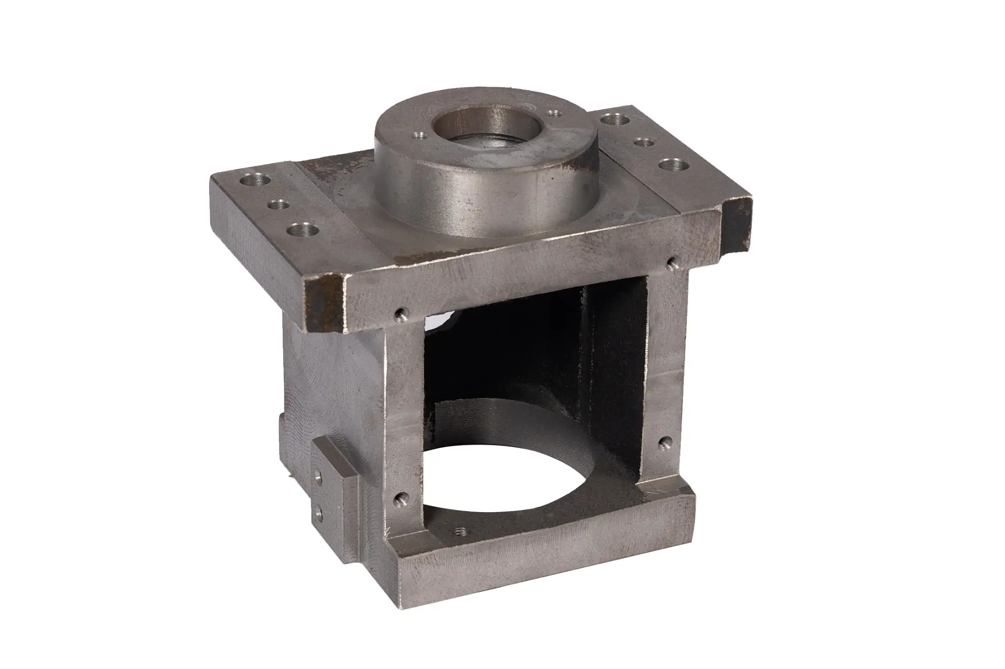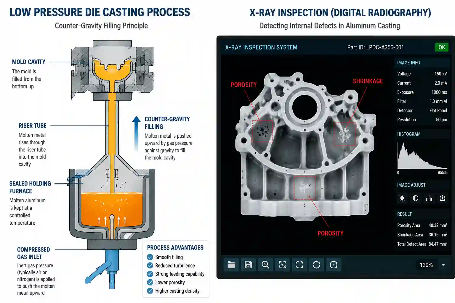



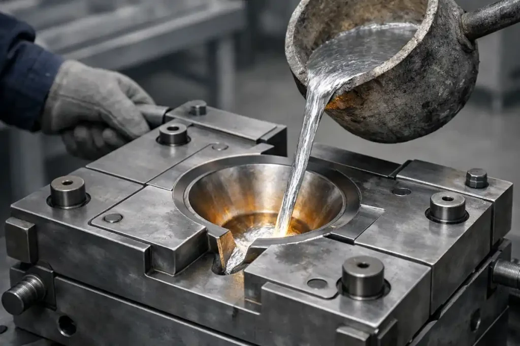
Gravity die casting is a manufacturing process in which molten metal is poured into a mold and fills the cavity under its own weight before cooling and solidifying into a finished casting. In aluminum component manufacturing, gravity die casting usually refers to gravity casting with reusable metal molds.
Strictly speaking, “gravity” describes the filling method, while “metal mold” describes the mold type. Sand casting can also rely on gravity to fill the mold, but it differs from gravity die casting in mold construction, cooling conditions, and production organization. The following sections mainly focus on aluminum gravity die casting with permanent metal molds.
What Is Gravity Die Casting?
Gravity die casting uses a reusable metal mold. Molten metal enters the cavity through a gating system and fills it under gravity. After cooling and solidification, the mold is opened, the casting is removed, and the mold can be reused for the next production cycle.
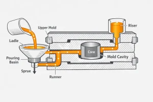
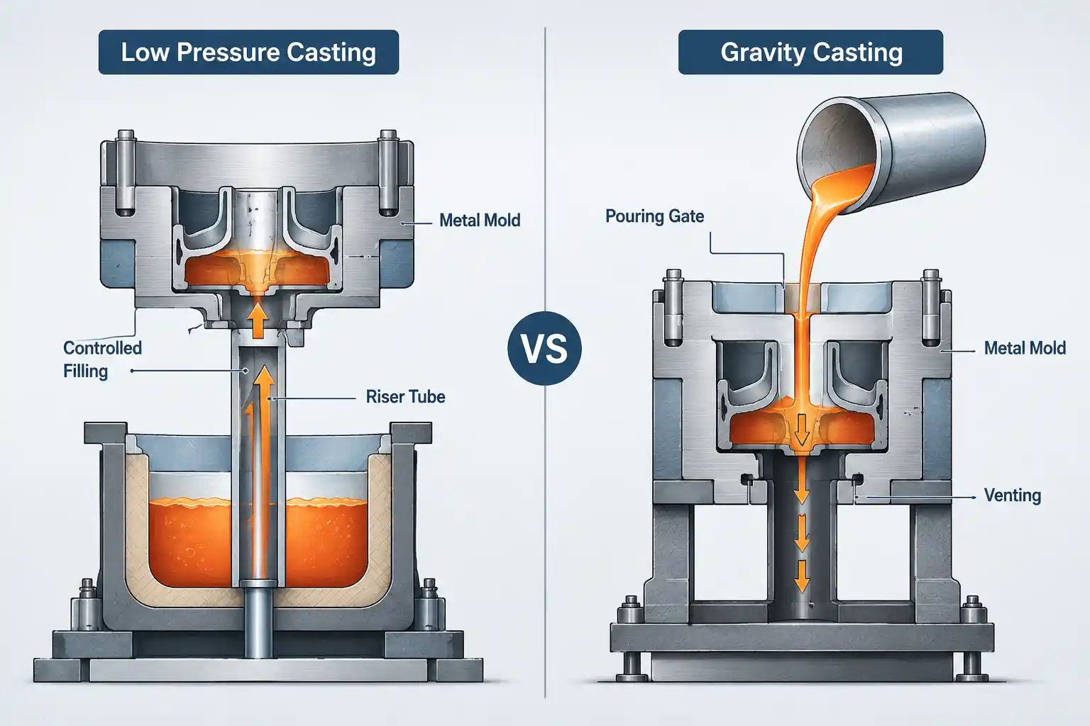
This process belongs to the permanent mold casting family and is commonly used for aluminum components. Its main difference from high-pressure die casting is the filling method. Gravity die casting does not use an injection system to force molten metal rapidly into the mold. Instead, metal flow is controlled through the gating system and mold layout.
How Does Gravity Die Casting Work?
The process mainly involves two tasks: completely filling the mold cavity and controlling how the casting solidifies. Mold preparation, pouring, and cooling must work together to produce a casting suitable for subsequent machining and finishing.
Mold Preparation and Preheating
The mold is first cleaned, preheated, and coated according to the process requirements. Preheating helps prevent the molten metal from losing heat too quickly when it contacts the mold, while the coating protects the mold and helps control local heat transfer.
If the component contains curved passages or internal features that cannot be released directly from the metal mold, sand cores can be installed before the mold is closed. These cores must be positioned accurately, otherwise the internal cavity may shift or local wall thickness may change.
Pouring and Filling
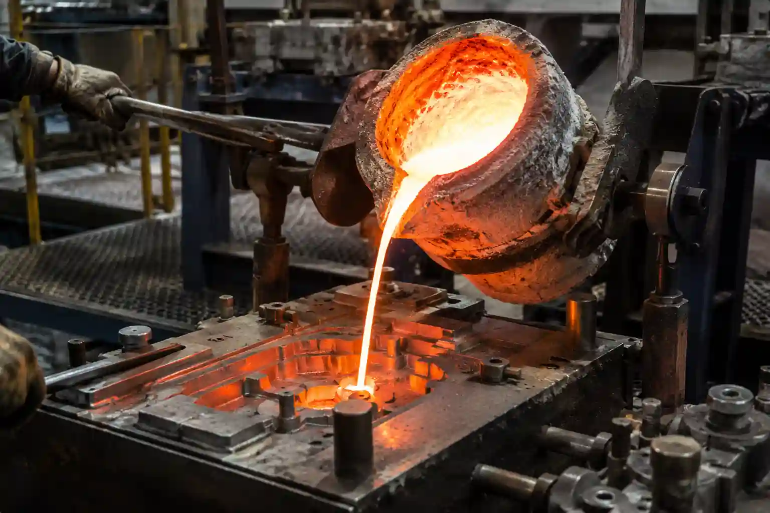
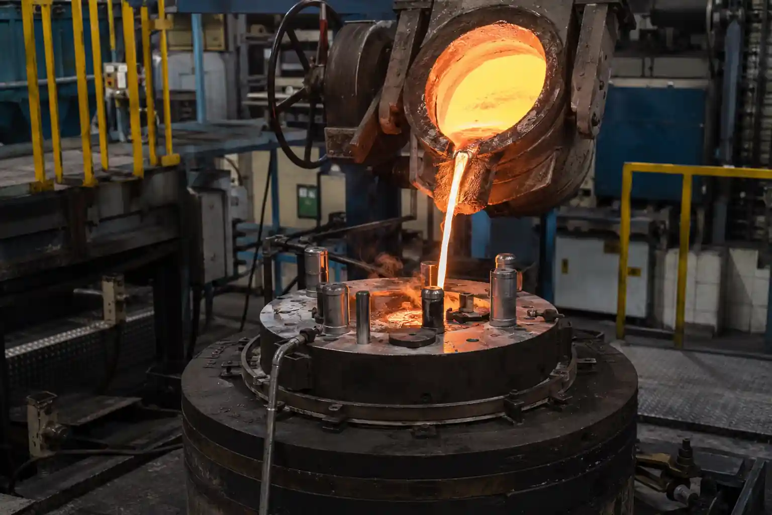
Prepared molten metal enters through the gate and is distributed throughout the cavity by the runner system. The gating system should guide the metal as smoothly as possible, while vents allow air in the cavity to escape and reduce the risk of trapped gas and oxide-film entrainment.
Pouring can be performed with a stationary mold or with tilt-pouring equipment that changes the mold orientation through controlled rotation. Tilting can help manage the flow path, but its effectiveness depends on how well the gating design matches the movement sequence.
Solidification and Feeding
Metal contracts during solidification, so regions that have not yet solidified need additional liquid metal to compensate for shrinkage. Risers store and supply molten metal, while local mold cooling can help control the solidification sequence.
Thicker sections tend to form hot spots and solidify later. If the feeding path freezes too early, shrinkage cavities or shrinkage porosity may remain. Feeding design therefore needs to consider both component geometry and local heat dissipation.
Mold Opening and Post-Processing
Once the casting reaches a suitable condition for removal, the mold is opened and the sand cores, gates, risers, and flash are removed. Ejection timing also needs to be controlled. Removing the casting too early may cause distortion, while removing it too late occupies the mold and extends the production cycle.
Depending on the drawing requirements, the casting may also undergo heat treatment, CNC machining, and surface finishing. Different alloys and applications require different process routes, so not every gravity-cast component receives the same post-processing.
What Materials Are Commonly Used in Gravity Die Casting?
Gravity die casting is mainly used for non-ferrous alloys such as aluminum, magnesium, and copper alloys. Aluminum alloys are particularly common in industrial component manufacturing. Cast aluminum alloys such as A356 and A357 are often used for housings, brackets, pump bodies, and structural components that may require subsequent machining or heat treatment.
Different alloys have different fluidity, solidification ranges, and heat-treatment responses. Material selection therefore affects mold filling, feeding, and thermal management. Long, thin-walled parts are more sensitive to heat loss and metal flow during filling, while thicker or load-bearing parts also require consideration of mechanical properties, heat-treatment condition, and final service requirements.
If the drawing already specifies an alloy, the casting process usually needs to be adjusted around that material rather than applying one fixed set of process parameters based only on component shape.
What Should Be Considered in Gravity Die Casting Design?
Gravity die casting design is not only about whether the final geometry can be formed. It also needs to consider whether molten metal can completely fill the cavity, whether the casting can solidify in a controlled manner, whether the mold can open properly, and whether subsequent machining can be carried out efficiently.
Wall Thickness and Section Transitions
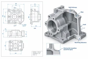
Wall thickness directly affects filling and solidification. Long, thin sections can lose fluidity before the metal fully reaches the end of the cavity, while thick sections cool more slowly and are more likely to form local hot spots.
Abrupt changes in section thickness should be avoided where possible. Flange roots, large bosses, and intersections between ribs can create local material accumulation and should be checked carefully for feeding and cooling conditions.
Fillets and Corners
Fillets can improve metal flow through the cavity and reduce local stress caused by abrupt section changes. Sharp corners can increase filling difficulty and may also create unfavorable local thermal and solidification conditions.
At structural junctions, gradual transitions are generally easier to control than sudden increases in section thickness.
Draft and Parting Lines
Permanent metal molds need to open repeatedly and release the casting, so the component geometry must consider the direction of withdrawal. Undercuts, deep cavities, and side features may require movable inserts, core-pulling mechanisms, or other auxiliary tooling.
The position of the parting line also affects mold construction and subsequent cleaning. Concentrating complex features in areas that are difficult to release can increase both tooling complexity and production effort.
Sand Cores and Internal Features
Internal passages, cavities, and features that cannot be formed directly by removable metal cores can be produced with sand cores. The cores must not only form the required geometry but also remain stable during pouring.
Core displacement can shift internal cavities, create uneven wall thickness, and affect machining allowance or assembly dimensions. Internal feature design therefore needs to consider core production, positioning, and removal.
Gating System and Filling Path
Gates and runners need to deliver molten metal to different regions of the cavity while minimizing excessive turbulence and unnecessary flow resistance. For components with long flow distances, overly long filling paths or abrupt changes in section can increase the risk of premature cooling at remote areas.
Venting also needs to be considered during design. If air cannot escape effectively, local gas entrapment can occur even when molten metal reaches the cavity.
Solidification and Hot-Spot Control
Thick flanges, large bosses, bearing seats, and rib intersections are common hot-spot locations. These regions usually solidify last, so feeding paths need to remain effective during the later stages of solidification.
Risers, local cooling, and wall-thickness adjustments can all be used to improve the solidification sequence. Compared with the overall component size, local material concentrations often have a greater influence on the risk of shrinkage cavities and shrinkage porosity.
Machining Allowance and Locating Datums
For components that require CNC machining, machining allowance and locating datums should be defined during casting design. If bearing seats, sealing surfaces, mounting holes, or threaded areas do not have enough allowance, later machining may not be able to achieve the drawing requirements.
The relationship between machined surfaces and hot-spot locations also needs attention. Internal shrinkage that is not visible in the as-cast condition may become exposed after machining on a sealing surface or bearing seat.
In practice, gravity die casting design needs to answer three questions at the same time: Can the metal fill the cavity? Can the casting solidify reliably? Can the casting blank support the required downstream machining?
Advantages and Disadvantages of Gravity Die Casting
Advantages
- More consistent dimensions in repeat production. Reusable metal molds can maintain a relatively stable cavity profile. When mold temperature and wear are controlled, machining allowance and the position of mounting features are easier to keep consistent.
- A finer surface than conventional sand castings in many cases. A metal cavity does not reproduce the granular texture of a sand mold, although the final surface still depends on mold coating, parting lines, and cleaning methods.
- Well suited to subsequent precision machining. The main body, bosses, and ribs can be formed by casting, while bearing seats, threaded holes, and sealing surfaces are machined afterward.
- Sand cores can be used to create internal passages. This expands the range of internal cavities that can be manufactured in a reusable metal mold.
- Some aluminum alloys can be heat treated. Cast aluminum alloys such as A356 and A357 can be heat treated to modify mechanical properties, although the final condition still depends on the material, application, and distortion risk.
Disadvantages
- Limited capability for long, thin-wall filling. Molten metal continuously loses heat to the mold as it flows, so long thin sections may begin to solidify before the cavity is completely filled.
- Higher initial tooling investment than conventional sand casting. Metal molds require machined cavities, opening and closing structures, and consideration of repeated thermal cycling.
- Production cycles are usually slower than high-pressure die casting. Gravity filling and solidification take time, while sand-core placement and mold cleaning can further extend cycle time.
- Complex geometry increases tooling and operating difficulty. Undercuts, deep cavities, and side features may require movable inserts, core-pulling systems, or sand cores.
If a drawing contains both long thin walls and thick flange roots, these areas should be checked carefully to determine whether they can be produced under the same process conditions. Local features like these often have more influence on manufacturing difficulty than the overall size of the part.
What Are Common Applications of Gravity Die Casting?
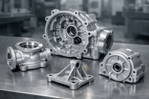
Gravity die casting is commonly used for aluminum components that have reached a relatively stable design stage and require repeat production. The final process choice still depends on size, geometry, and production volume.
Automotive
- Cylinder heads
- Some engine blocks
- Intake manifolds
- Engine mounting brackets
These components may combine internal passages, load-bearing structures, and machined surfaces, so forming method, material properties, and downstream machining requirements need to be evaluated together.
Industrial Machinery
- Gearbox housings
- Bearing housings
- Equipment end covers
- Machine mounting brackets
These parts often have moderate wall thickness, mounting bosses, or clearly defined fit features. Once the main geometry is established, cast blanks can be produced repeatedly and precision machining can be concentrated on local functional areas.
Fluid and Energy Equipment
- Aluminum pump housings
- Valve bodies
- Hydraulic system housings
- Actuator housings
These components often include internal passages, connecting flanges, or sealing areas. Casting capability therefore needs to be considered together with final functional requirements. For pressure-containing or fluid-handling components, leak testing and pressure testing requirements should also be defined. Acceptable appearance and dimensions alone do not prove that a component will meet sealing requirements.
How Does Gravity Die Casting Compare with Other Casting Processes?
| Comparison | Gravity Die Casting | Sand Casting | High-Pressure Die Casting |
|---|---|---|---|
| Filling method | Mainly gravity filling | Usually gravity poured, although other methods are possible | Rapid filling through an injection system |
| Mold type | Reusable metal mold, can be combined with sand cores | Expendable sand mold; patterns can be reused | Reusable metal mold |
| Thin-wall capability | Limited by alloy, wall thickness, and flow distance | Limited by molding and filling conditions | High-speed filling is generally better suited to thin walls |
| Production cycle | Influenced by pouring, solidification, and ejection time | Varies widely; automated lines can also achieve high output | Usually faster and suited to continuous production |
| Tooling investment | Usually higher than basic sand-casting tooling | Simple tooling is generally less expensive | Tooling and equipment investment are usually higher |
| Production volume | Tooling cost needs to be spread over repeat production | Can be used from low volume to mass production depending on the system | Usually requires higher volume to justify the initial investment |
| Typical parts | Housings, cylinder heads, pump bodies, brackets | Large housings, machine bases, complex castings | Thin-wall housings, covers, high-volume structural parts |
Sand casting uses expendable molds and is more flexible for some large components, complex structures, or products that are still changing frequently. It can also support high-volume production, so it should not be understood as a process used only for low-volume work.
Gravity die casting uses reusable metal molds to produce casting blanks and is better suited to relatively stable designs with continuing production demand, especially when internal cavities and subsequent machining are also required. Its economic suitability depends on whether tooling cost can be spread across actual production volume and whether downstream machining cost is acceptable.
High-pressure die casting uses rapid filling to improve thin-wall forming capability and is better suited to short cycle times and continuous high-volume production. However, both tooling and equipment investment are generally higher. When production volume is sufficiently large and the component has complex thin-wall requirements, high-pressure die casting may become a more suitable option.
Conclusion
Gravity die casting is well suited to aluminum components with stable designs, repeat production requirements, and local features that require precision machining. Process selection should pay particular attention to material, wall-thickness transitions, filling paths, hot spots, core structures, and downstream machining requirements.
Rather than judging the process only by overall part size or casting price, it is more useful to determine whether all of these conditions can be satisfied within the same manufacturing route.