


In metal casting, molten metal enters the mold cavity through a gating system. The arrangement of these passages affects whether the metal fills the mold completely and whether defects such as cold shuts, misruns, and inclusions develop.
The following sections explain the components of a gating system, the differences between pressurized and unpressurized systems, and the main considerations in their design.
What Is a Gating System?
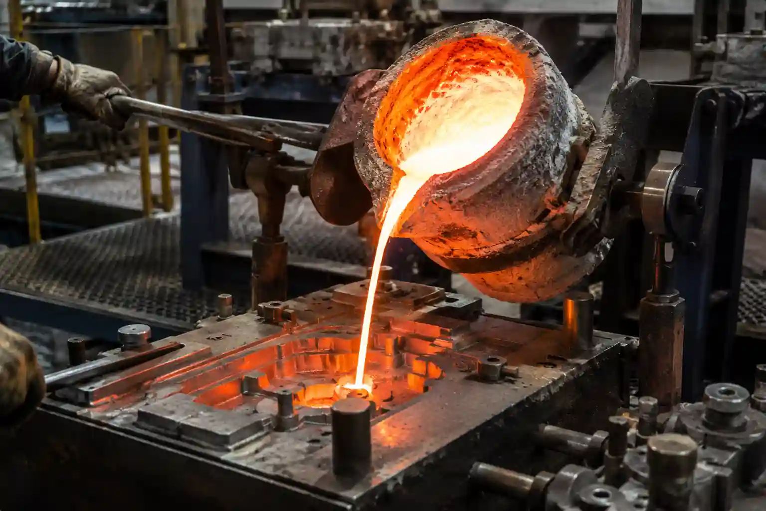
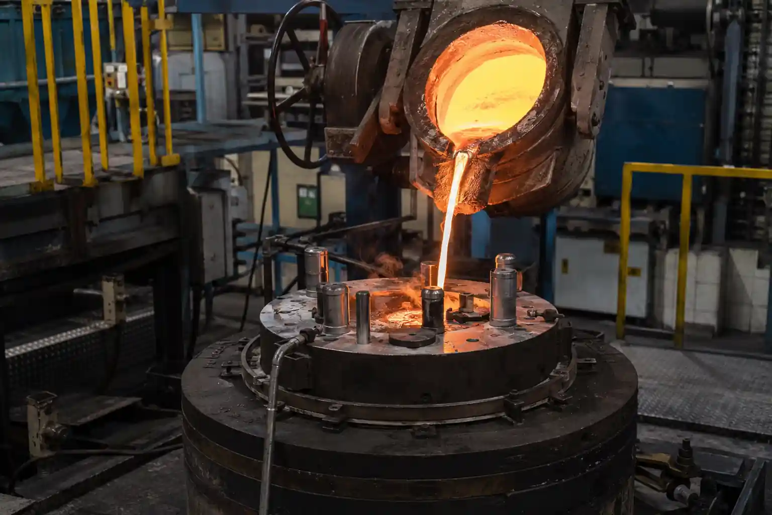
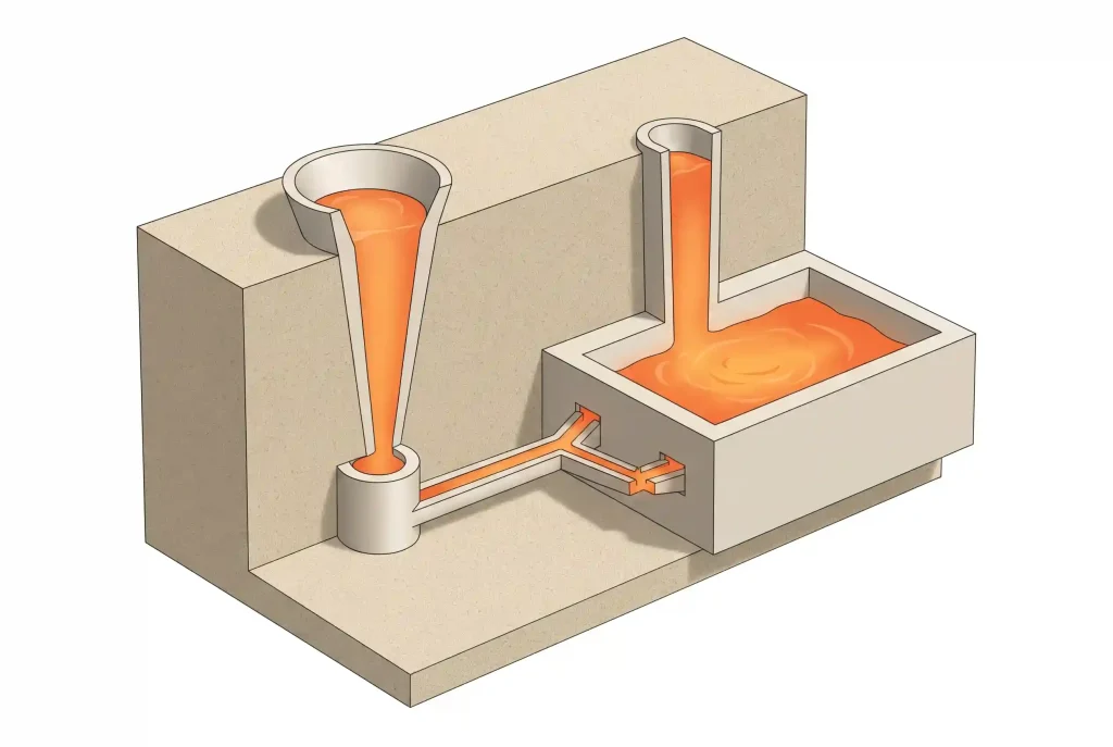
A gating system is a network of passages that carries molten metal from the pouring entrance into the mold cavity. During pouring, the metal travels down the sprue, passes through the runners, and enters the cavity through the ingates.
Gating systems are used in sand casting, investment casting, and gravity die casting. Their configurations vary, but each requires a flow path suited to the alloy and component geometry.
Besides delivering molten metal, the gating system controls flow rate and velocity. Excessive velocity can increase splashing, air entrainment, and mold erosion. Filling too slowly can allow the metal to begin solidifying before the cavity is full, causing cold shuts or misruns.
Main Components of a Gating System
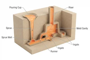
A typical gating system consists of a pouring cup, sprue, sprue well, runner, and ingates. Each component performs a different task along the metal’s path into the cavity.
Pouring Cup
The pouring cup sits at the entrance to the gating system. It receives molten metal from the ladle and supplies it to the sprue.
Its capacity should support a continuous supply during pouring. The cup’s shape and metal level also affect splashing and vortex formation, so its design should help limit air entering the sprue with the metal.
Sprue and Sprue Well
The sprue is located below the pouring cup and guides molten metal downward. As the metal accelerates during its descent, the stream’s cross-sectional area changes. Sprues therefore commonly taper from a wider top to a narrower bottom, helping reduce gaps between the stream and the passage that could draw in air.
The sprue well is a transition space at the base of the sprue. Here, the metal changes direction and enters the runner. A suitable transition helps reduce impact and sand erosion at the turn.
Runner
The runner connects the base of the sprue to the ingates and distributes molten metal. When several ingates are used, the metal travels along the runner to reach the different cavity entrances.
Runner length, cross-sectional area, and branch positions affect the supply to each ingate. Runner extensions, slag traps, or filters may also be incorporated to help keep some inclusions out of the casting.
Ingate
The ingate is the opening through which molten metal enters the mold cavity. Its position and direction influence where filling begins and how it progresses.
The number and total cross-sectional area of the ingates also affect entry velocity. After solidification, the gate connections usually require removal and cleaning, so their placement should allow tool access without damaging the component’s surface.
Types of Gating Systems in Casting
The same basic components can form pressurized or unpressurized gating systems by changing the cross-sectional area relationships between the sprue, runners, and ingates.
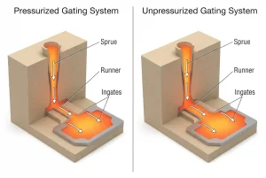
Both systems have a choke that controls flow. Their differences lie in the choke’s location and how passage areas are distributed upstream and downstream.
Pressurized Gating System
A pressurized system typically controls flow near the ingates. The relatively small total ingate area restricts discharge at the end of the system, helping the upstream passages remain full.
These systems generally have compact gating passages that consume less metal. However, at the same flow rate, a smaller total outlet area produces a higher average entry velocity. If the stream strikes a core or mold wall directly, it can increase sand erosion, splashing, and air entrainment.
“Pressurized” refers to the flow restriction created within the gating system. It does not mean that a die casting machine injects the metal into the cavity.
Unpressurized Gating System
An unpressurized system typically controls flow near the base of the sprue, with larger total cross-sectional areas in the downstream runners and ingates.
This arrangement can lower the average downstream velocity and reduce impact as metal enters the cavity. It is commonly used for aluminum castings where limiting oxide-film entrainment is important.
The filling and distribution of metal through the enlarged passages still require attention. Free-falling streams or uneven supply between branches can cause air aspiration and unstable filling.
Gating System Design
Once the system type is understood, passage dimensions and entry arrangements must be developed for the component. Design usually begins with filling requirements, followed by the runners, ingates, filtration, and venting. Feeding during solidification must also be assessed.
Filling Time and Velocity
Filling time is the time required for molten metal to fill the mold cavity. It depends on the alloy, casting weight, minimum wall thickness, and pouring temperature.
Thin sections lose heat quickly. If the metal reaches them too late, they may not form completely. Increasing velocity without considering the flow pattern, however, can cause splashing and air entrainment. A suitable filling time should therefore be established before sizing the passages to deliver enough metal.
Velocity and filling time are related but different. A high velocity at one ingate does not necessarily mean the entire cavity fills quickly. Total ingate area and the volume of metal required also matter.
Passage Dimensions and Gating Ratios
Passage dimensions affect both the quantity of metal that can pass through and its velocity. The areas at the sprue base, runners, and ingates should therefore be considered together.
A gating ratio is commonly expressed as:
Reference sprue cross-sectional area : total runner cross-sectional area : total ingate cross-sectional area.
Where multiple runners or ingates are used, their corresponding areas must be added together. Passage width and depth both matter; comparing widths alone does not establish the area relationship.
After selecting an initial ratio, the effects of passage length, turns, and filter resistance should be checked. Simulation or trial castings can then guide adjustments.
Metal Entry Position
Metal can enter the cavity from an upper, lower, or side position. Common arrangements include top gating, bottom gating, and parting-line gating.
Top gating introduces metal into the upper part of the cavity and can provide a short flow path. However, a large drop can increase splashing and sand erosion.
Bottom gating introduces metal into the lower part of the cavity, allowing the liquid level to rise progressively. This reduces the impact associated with a high falling stream, but the metal must retain enough filling capability to reach the upper and remote sections.
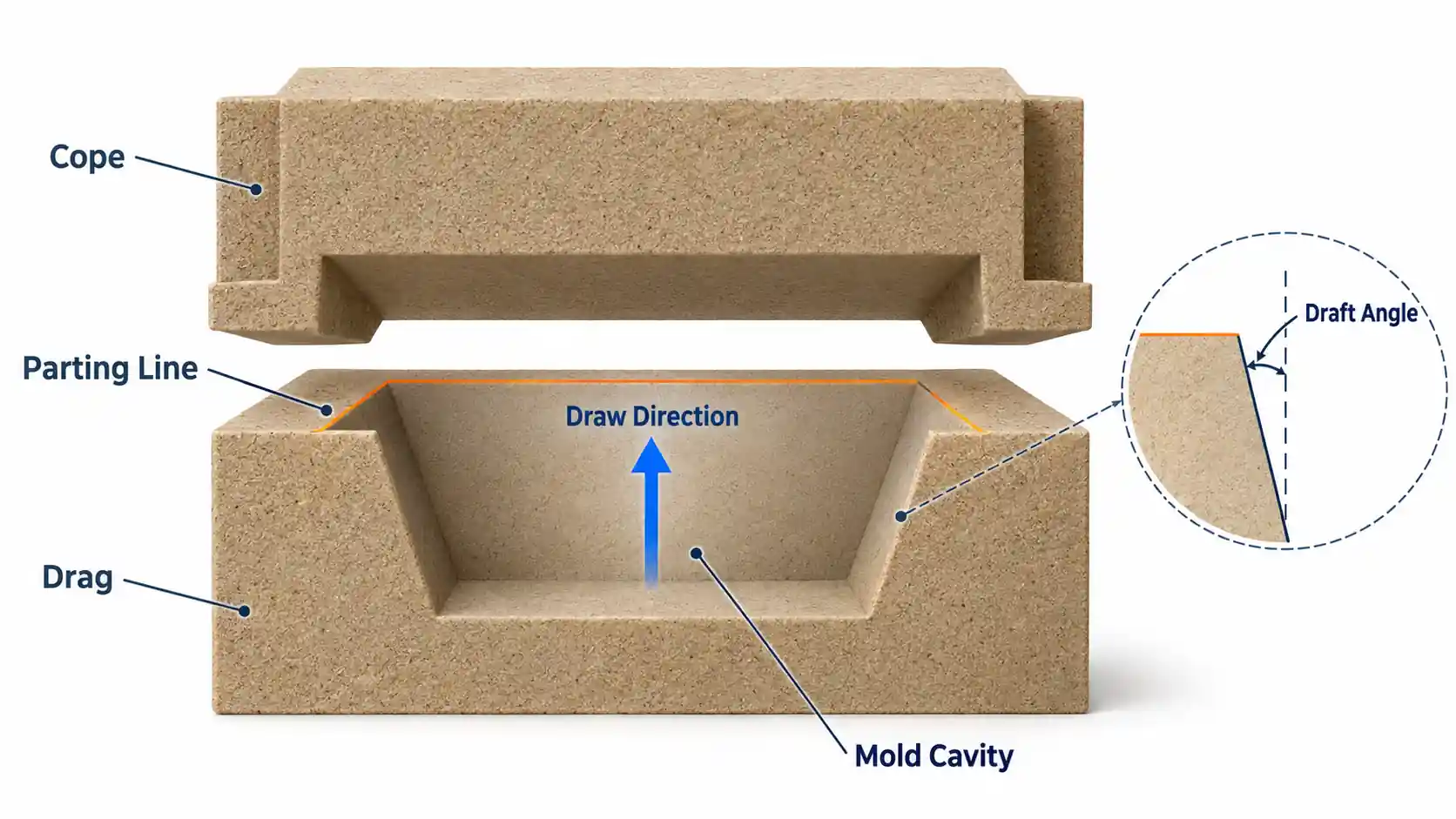
Parting-line gating places the ingates near the mold’s parting plane, making them convenient to incorporate into molding. How the metal fills the upper and lower regions depends on the parting-plane position and component geometry.
Ingate Layout
Ingates should guide metal into the cavity while avoiding unnecessary flow distance. Streams should not strike slender cores or weak mold walls directly.
For large components or geometries with widely separated sections, multiple ingates can shorten local flow paths. They also create meeting points between streams, so arrival times and meeting locations require attention. If the streams meet at too low a temperature, cold shuts may form.
Ingates also affect local temperature distribution. Their positions should be checked for the formation of heavy hot spots that may be difficult to feed.
Slag Control and Filtration
Inclusions can travel with the molten metal into the cavity. Runner extensions, slag traps, and ceramic filters can help reduce the amount reaching the casting.
Filters should be selected for the alloy, pouring temperature, and flow rate. Insufficient filter area or excessive resistance can extend filling time. After adding a filter, the system should be checked to confirm that the cavity can still fill within the intended time.
Venting
As metal fills the cavity, the air already inside must escape. Sand molds and cores may also generate gas when heated, so venting should be coordinated with the filling path.
High points, blind pockets, and last-to-fill regions require particular attention. Depending on the molding process, gas can escape through sand permeability, vent holes, or other vent passages. These routes should remain available rather than being sealed by metal too early.
Feeding and Solidification
The gating system delivers metal into the cavity, while risers provide additional molten metal to compensate for solidification shrinkage.
A riser is a reservoir connected to the mold cavity. It fills during pouring, and as the casting solidifies and contracts, liquid metal from the riser feeds into the casting through the connection.
The riser needs sufficient capacity and must remain liquid long enough to provide the required feed metal. If the connection freezes too early, feeding stops even if liquid metal remains in the riser. Gate and riser positions should therefore be considered together and assessed through trial castings, simulation, and inspection.
Conclusion
Pressurized and unpressurized gating systems use similar basic components. Their main differences are the cross-sectional area relationships between passages and the location where flow is controlled.
Design should allow metal to fill the cavity in time while limiting splashing, air entrainment, and mold erosion. Once passage dimensions and ingate positions are established, filtration, venting, and feeding should also be checked. Trial castings and inspection results can then guide further adjustments.