


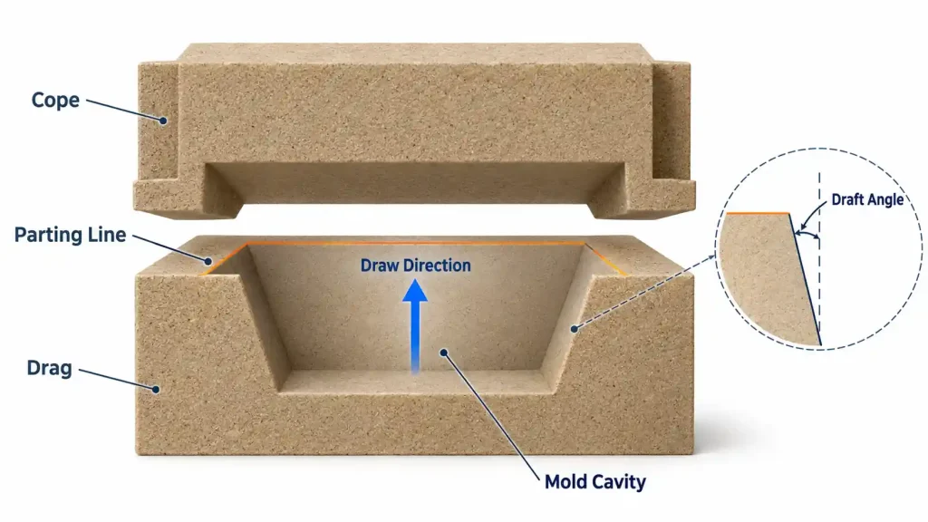
The molding arrangement in sand casting affects pattern construction, core assembly, mold alignment, and subsequent machining. The parting line marks where mold sections meet, while draft angles help the pattern separate from the sand during withdrawal. For parts with deep pockets, ribs, bosses, or machined interfaces, these design choices also affect local wall thickness, dimensional references, and machining stock.
What Are Draft Angles and Parting Lines?
Draft Angle
A draft angle is the taper applied to a pattern surface relative to the direction of withdrawal. This taper allows the surface to separate progressively from the sand as the pattern is removed.
Without draft, a straight wall may remain in contact with the mold throughout much of the withdrawal stroke. Surface roughness, misalignment during withdrawal, or poorly supported sand edges can cause dragging, cavity damage, and broken corners. Draft creates clearance as the pattern moves, although the result still depends on pattern condition and molding practice.
In conventional sand casting, the pattern is removed before pouring. The solidified casting is later separated from the sand during shakeout. Pattern withdrawal therefore involves different conditions from removing a solidified casting from a permanent metal mold.
Parting Line
The parting surface is the interface between adjoining mold sections. In a typical horizontally parted, two-part mold, it is the interface between the cope and drag. Where this interface intersects the casting surface, it forms the parting line.
The parting surface and parting line describe different geometries. For example, a cylinder parted across its mid-height can have a flat parting surface and a circular parting line. A flat parting surface does not require a straight line on the casting.
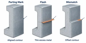
A visible seam often follows the parting line. Thin excess metal formed in a gap at the interface is flash, while a step caused by misalignment between mold sections is mismatch. American Foundry Society: Metalcasting Terms
How Is the Parting Line Selected in Sand Casting?
Whether the Pattern Can Be Withdrawn
Parting-line location is first constrained by part geometry. Each pattern section needs a clear withdrawal path. Side bosses, reverse-facing recesses, and other undercuts can obstruct that movement.
For a symmetrical part, the plane of symmetry is often a useful starting point. For a complex housing, different orientations need to be examined to establish which surfaces can be molded directly and which require loose pieces or cores.
Parting on a single plane generally simplifies pattern construction and mold assembly. Stepped or contoured parting surfaces can accommodate more complex shapes, but they add work to manufacturing, locating, and inspecting the interface. SFSA: Parting-Line Design Guidance
How Critical Dimensions Are Formed
A dimension may be formed entirely within one mold section, across the cope and drag, or between a mold surface and a core. Each arrangement has different sources of variation. These relationships also matter when specifying aluminum casting tolerances.
For example, consider an as-cast cylindrical profile formed partly by the cope and partly by the drag. Lateral displacement between the sections can create a step at the joint. For a height dimension crossing the parting interface, an assembly gap can also affect the result.
Where machining is required, sufficient stock must remain after casting variation to achieve the finished geometry. Checking only an average overall dimension can overlook a local shortage of material.
Core Assembly and Functional Surfaces
The parting arrangement needs to provide access for core assembly, positioning, and inspection before mold closure. A location that makes the main pattern easy to withdraw may make a core difficult to install or cause interference during closing.
Parting marks also affect downstream work on sealing faces, mating surfaces, and visible areas. Surfaces left as cast must meet their profile and cleaning requirements directly. Machined surfaces need sufficient stock to remove acceptable seam marks and dimensional variation.
Parting-line selection therefore involves comparing pattern withdrawal, core assembly, dimensional control, and machining requirements.
What Are Typical Draft Angles for Sand Casting?
External surfaces, deep pockets, and narrow rib spaces have different withdrawal conditions. A single part may therefore use several draft angles.
The following values are typical recommendations from published steel-casting design guidance:
| Molding Process | Most Features | Deep Pockets |
|---|---|---|
| Green sand — manual molding | 1.5° | 2.0° |
| Green sand — automated molding | 1.0° | 1.5° |
| No-bake and shell molding | 1.0° | 1.5° |
Source: SFSA Supplement 3: Dimensional Capabilities of Steel Castings, Table 2.1. These recommendations concern steel castings and should not be treated as universal requirements for aluminum sand castings or other projects.
Which Conditions Affect Draft Selection?
Draw depth is the distance a surface extends along the withdrawal direction. Deeper features have a longer contact path, making pattern misalignment and local friction more significant.
Narrow recesses and closely spaced ribs can leave thin sections of sand between features. Their support conditions differ from those of an open external surface. Scratches, joints, damaged coatings, and wear on the pattern can also produce different withdrawal results at the same nominal angle.
When damage repeatedly occurs in one location, the local pattern surface and withdrawal movement need examination. Increasing draft everywhere may alter the part profile without removing the original cause.
What Do “Standard Draft” and “Minimum Draft” Mean?
A typical value in a design guide, an internal foundry rule, and the minimum angle used on a particular feature serve different purposes.
Typical values provide a design starting point. Internal rules usually reflect specific pattern materials, molding equipment, and production experience. Whether a feature can use less draft depends on its actual withdrawal performance.
Some features can be formed with cores, changing their dependence on draft in the main pattern. However, cores still require manufacture, positioning, and removal. With conventional core boxes, the opening arrangement and core extraction conditions also constrain the geometry.
Why Not Simply Increase the Angle?
A larger angle creates withdrawal clearance more quickly, but it also produces a greater change in profile along the height of the feature.
On a tall housing wall, that change may consume assembly clearance. On a thin-walled structure, the relationship between internal and external tapers may change the minimum wall thickness. On a machined surface, it changes the amount of stock along the cutting path. A suitable angle must accommodate both molding conditions and the finished part geometry.
How Do You Calculate a Draft Angle?
Calculating the Angle from Height and Offset
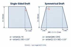
For a straight, single-sided tapered surface:
α = arctan(Δ ÷ H)
Where:
- α is the draft angle.
- H is the height measured along the withdrawal direction.
- Δ is the lateral offset between the two ends of that surface.
Suppose the draw height is 50 mm and the single-side lateral offset is 1 mm:
α = arctan(1 ÷ 50) ≈ 1.15°
When using a calculator, check that the inverse-tangent result is expressed in degrees. This example establishes a geometric angle; it is not a recommended process setting.
Calculating Symmetrical Draft on Two Sides
If two opposing surfaces have equal, symmetrical draft, the total width difference includes the change on both sides.
The angle on each side is:
α = arctan[Total width difference ÷ (2 × H)]
For example, if the width changes by 2 mm over a height of 50 mm, each side contributes 1 mm. The draft angle on each side is approximately 1.15°.
If only one side is tapered, or the two sides have different angles, they must be calculated separately. Dividing the total width difference by two would not describe those geometries correctly.
Calculating Dimensional Change from a Known Angle
If the angle and height are known, the single-side offset is:
Δ = H × tan α
For a height of 50 mm and a draft angle of 1°:
Δ = 50 × tan 1° ≈ 0.87 mm
At the same angle, a taller feature produces a larger lateral change. This calculation helps assess end dimensions, assembly clearances, and machining stock.
How Does Draft Affect Wall Thickness and Machining?
Housing wall thickness depends on both the internal and external surfaces. If the external profile widens toward one end while the internal profile remains unchanged, the wall becomes thicker at that end. A different arrangement may reduce the local section instead.
Ribs behave similarly. Their tip and root thicknesses can differ because of draft, while the combination of a tapered rib and a root fillet can create a locally heavy section. Section checks therefore need to cover different heights rather than one nominal wall thickness.
If a drafted wall will later be machined into a vertical surface, the distance between the complete cast profile and finished profile must also be checked. One end may have ample stock while the other cannot clean up fully. This needs to be coordinated with the dimensions, walls, and datums in the overall sand casting design.
How Can Parting Lines and Their Surface Marks Be Reduced?
Simplifying the Parting Arrangement
Reducing parting-line complexity starts with pattern sections and withdrawal paths. Where the geometry permits, removing unnecessary steps, changes in direction, and additional pattern pieces can simplify locating, cleaning, and inspection.
However, forcing a single-plane arrangement may introduce undercuts, thin sand sections, or difficult withdrawal elsewhere. The comparison needs to cover the complete molding process rather than only the length of the visible line.
Distinguishing Flash from Mismatch
Flash and mismatch can occur near the same parting line, but they require different checks.
| Casting Surface Condition | Main Items to Check |
|---|---|
| Thin excess metal along the joint | Interface gap, damaged parting surfaces, mold restraint during pouring |
| A step between profiles on opposite sides of the joint | Locating components, flask condition, cope-and-drag alignment |
| Repeated irregular depressions or projections in one location | Local pattern condition, sand damage, interference during mold closure |
Loose sand on the interface, worn locating components, and locally crushed mold surfaces can affect assembly. Relating the casting defect to the corresponding pattern, mold, and locating features helps identify where the problem originates.
What Can Cleaning and Machining Remove?
Cutting and grinding can remove flash and local excess metal. On surfaces left as cast, the cleaned area also needs examination for depressions, discontinuous profiles, or excessive wall thinning.
Sealing faces, bearing interfaces, and precision mounting surfaces are generally machined to establish their specified dimensions and surface requirements. Machining can remove parting marks within an available stock allowance. It cannot replace material already missing because of mold mismatch.
Acceptance requirements also affect the manufacturing route. “Remove flash” mainly defines a cleaning result. “No visible parting marks” involves the parting location, casting condition, and subsequent machining or finishing, so it represents a different scope of work.
Conclusion
Draft angles and parting lines jointly affect pattern withdrawal, mold alignment, and machining conditions. Parting arrangements need to account for withdrawal paths, core assembly, and critical dimensions. Draft selection requires an assessment of molding conditions and the resulting profile changes. Flash and mismatch near the parting line should be identified separately before deciding whether the correction belongs in design, mold assembly, or cleaning.
For an aluminum sand casting project, send MinHe your 2D drawings, 3D model, alloy specification, and critical machining requirements. Contact us to discuss the parting arrangement, draft angles, wall distribution, and machined surfaces.