


Navigating aluminum casting tolerances requires a shift from viewing a part as a single unit to understanding it as the result of complex manufacturing variables. Factors such as the chosen casting process, alloy shrinkage behavior, wall thickness, and inspection methodology directly dictate the dimensional consistency of your component.
Buyers and engineers should avoid assuming that all aluminum casting processes achieve the same tolerance level. Instead, initiate a technical discussion with your foundry regarding critical dimensions, machining allowances, and datum points before finalizing your tooling and inspection plans. Effectively separating as-cast requirements from final machined specifications remains the most reliable way to optimize both component performance and unit cost.
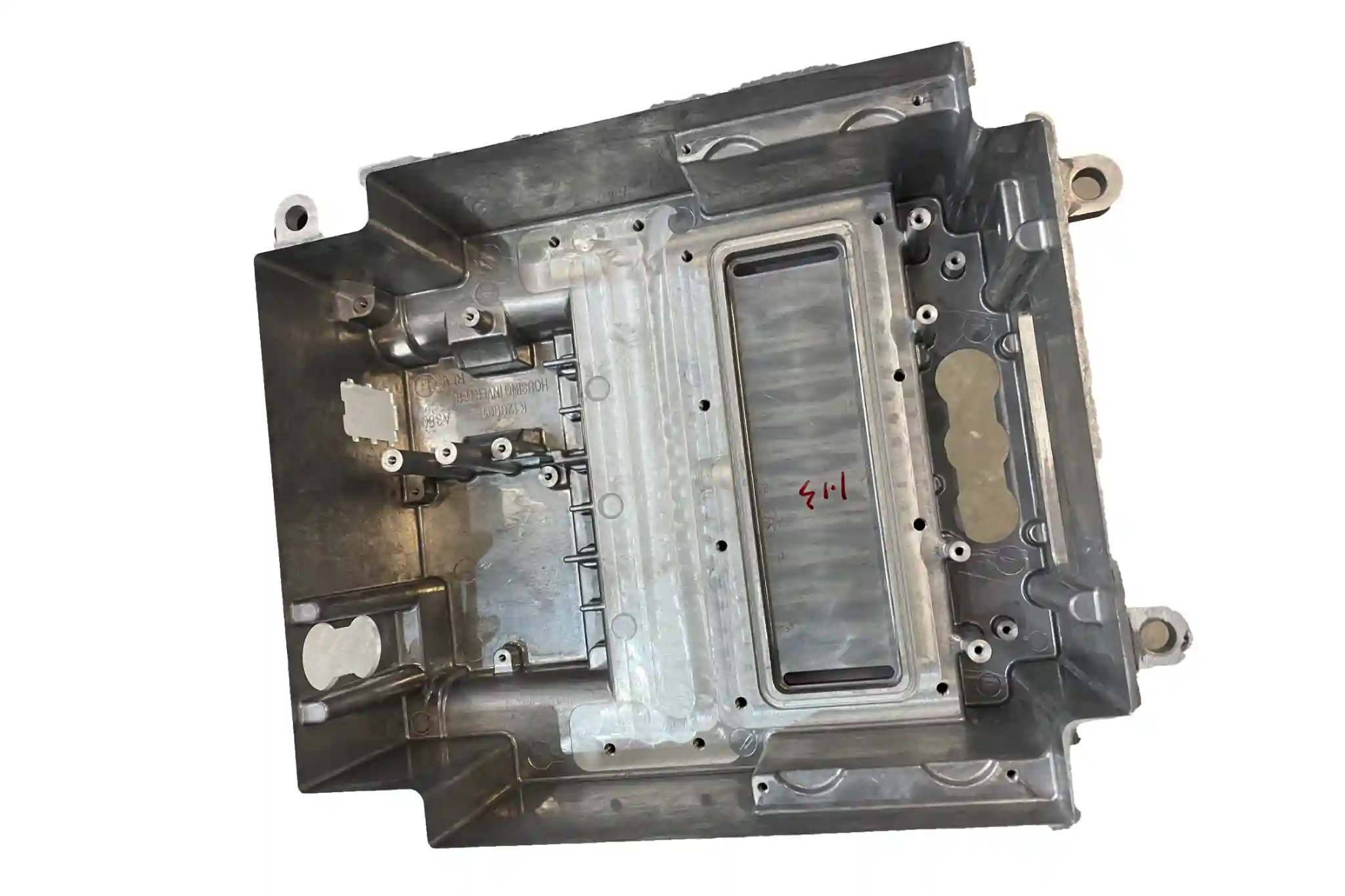
Quick Reference: Aluminum Casting Tolerance by Process
Actual tolerances depend on part geometry, alloy, drawing standard, mold condition, inspection method, and foundry capability.
| Casting Process | Typical Tolerance Capability | Suitable Parts | Notes |
| Sand Casting | ±0.5mm – ±1.5mm | Large structural parts | Suitable for low volume production. |
| Gravity Die | ±0.3mm – ±0.8mm | Pump bodies, valve housings | Provides consistent surface finish. |
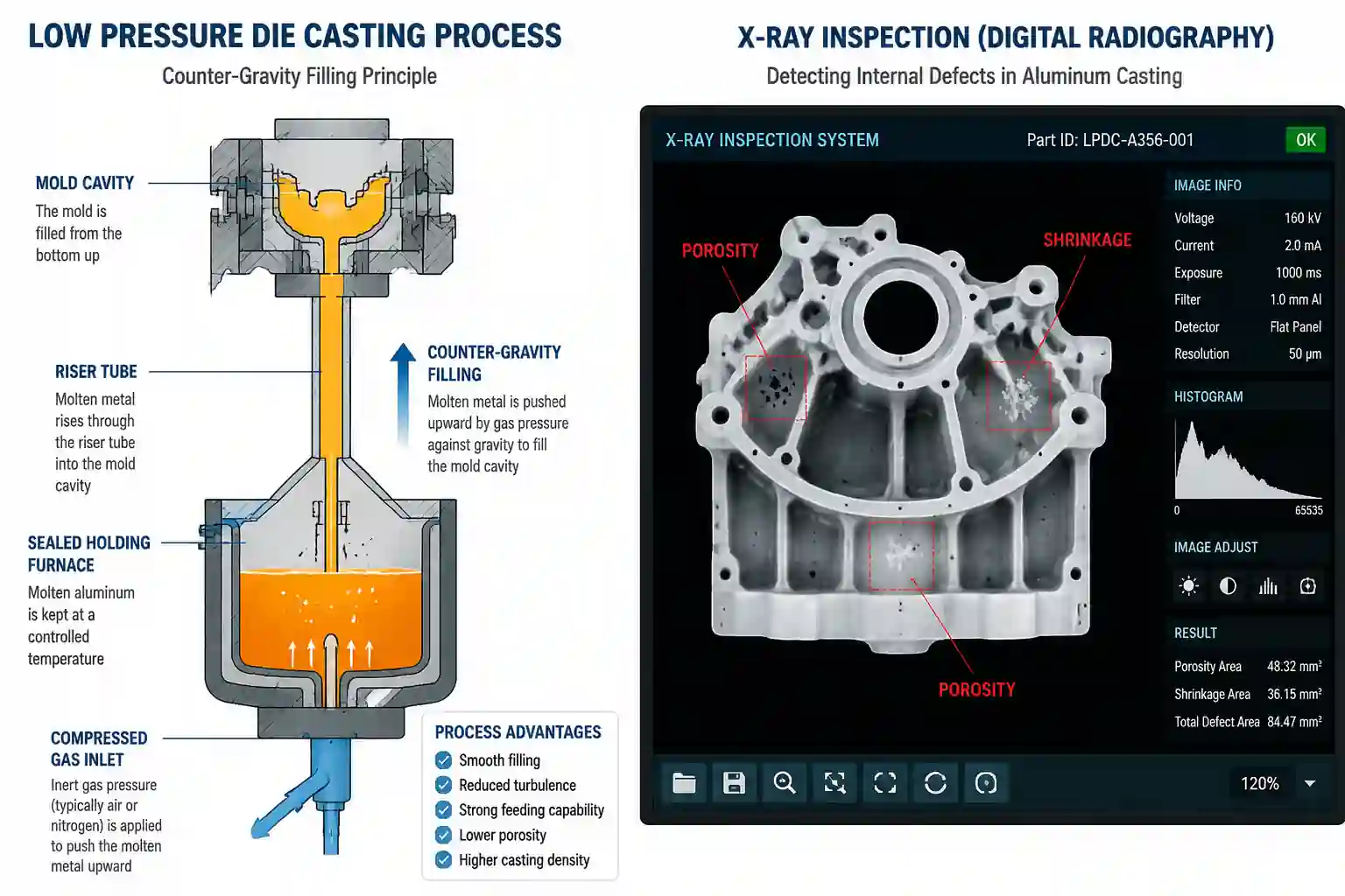
| Low Pressure | ±0.2mm – ±0.5mm | Wheels, cylinder heads | Supports complex internal geometry. |
| High Pressure | ±0.1mm – ±0.3mm | Thin-wall covers, brackets | Common for high volume production. |
| Investment | ±0.1mm – ±0.2mm | Complex intricate shapes | Used for small, detailed components. |
Why Aluminum Casting Tolerances Vary
Dimensional variation in aluminum castings is rarely the result of a single factor. Understanding how these elements interact helps in setting realistic expectations for your project.
Casting Process
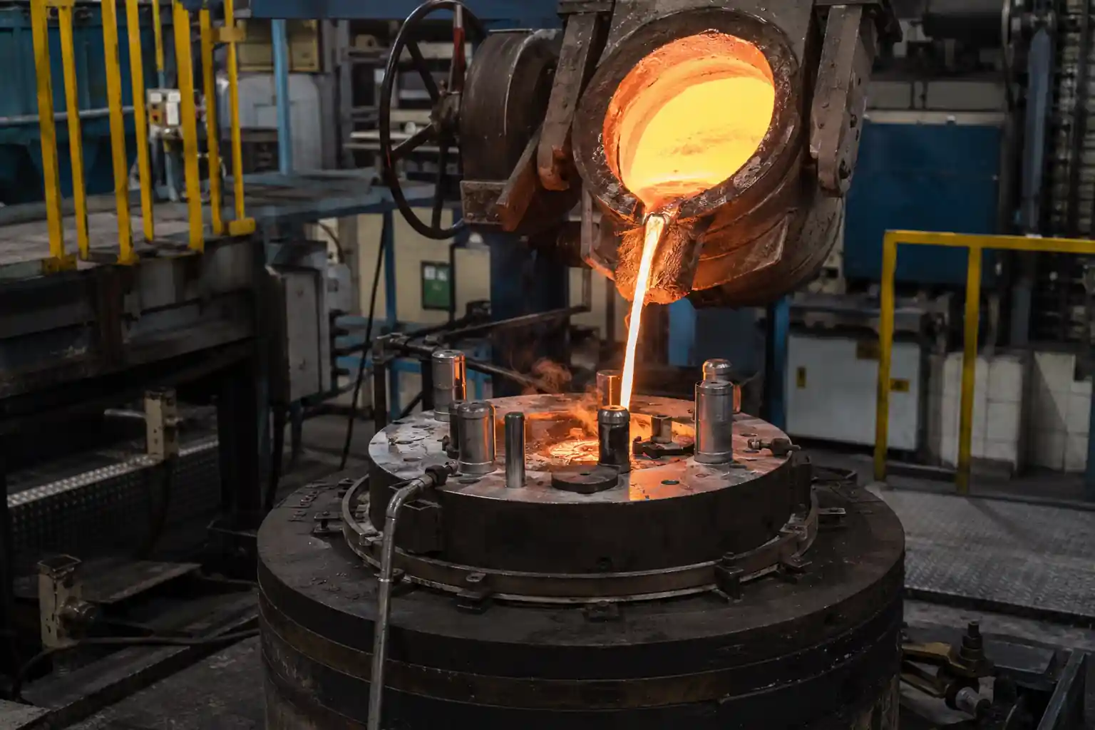
Each process possesses inherent constraints. High-pressure die casting provides rapid solidification and repeatability, whereas sand casting is prone to larger dimensional shifts due to the nature of mold sand compaction.
Alloy Shrinkage
Aluminum alloys shrink at different rates during cooling. If the specific shrinkage factor for your chosen alloy is not accurately integrated into the mold design, it leads to dimensional drift across the entire part.
Mold Type and Mold Wear
Steel dies hold tolerances longer than sand molds, which can deform during the pour. Over time, die erosion or thermal fatigue can shift dimensions, necessitating periodic maintenance.
Part Size and Wall Thickness
Larger parts are subject to greater thermal expansion and contraction. Thin-wall sections may cool faster than thicker sections, leading to potential warping or uneven shrinkage if the gating system is not optimized.
These dimensional issues may also appear together with aluminum casting defects when feeding, cooling, or mold design is not properly controlled.
Draft Angle and Parting Line
To ensure a part can be removed from the mold, draft angles are required. Dimensions across the parting line often have a wider tolerance range than dimensions within a single mold half.
Core Shift
Internal cavities are formed by cores. If a core is not perfectly secured, it may shift slightly under the pressure of molten metal, causing wall thickness inconsistencies that affect internal passage alignment.
Heat Treatment Distortion
The quenching process used for heat-treating aluminum alloys can introduce stress. Depending on the part’s geometry, this often results in subtle bowing or twisting, which may require straightening or secondary machining.
Machining Allowance
If a surface requires subsequent CNC work, material must be added to the raw casting. If this allowance is insufficient, the machining process may fail to fully clean up the surface, leading to dimensional failure or residual casting skin.
Inspection Datum and Measurement Method
Consistency between the foundry’s inspection methods and your assembly requirements is essential. Using different datum points for measurement often leads to discrepancies between the supplier’s report and your QC results.
Casting Tolerance vs. Machining Tolerance
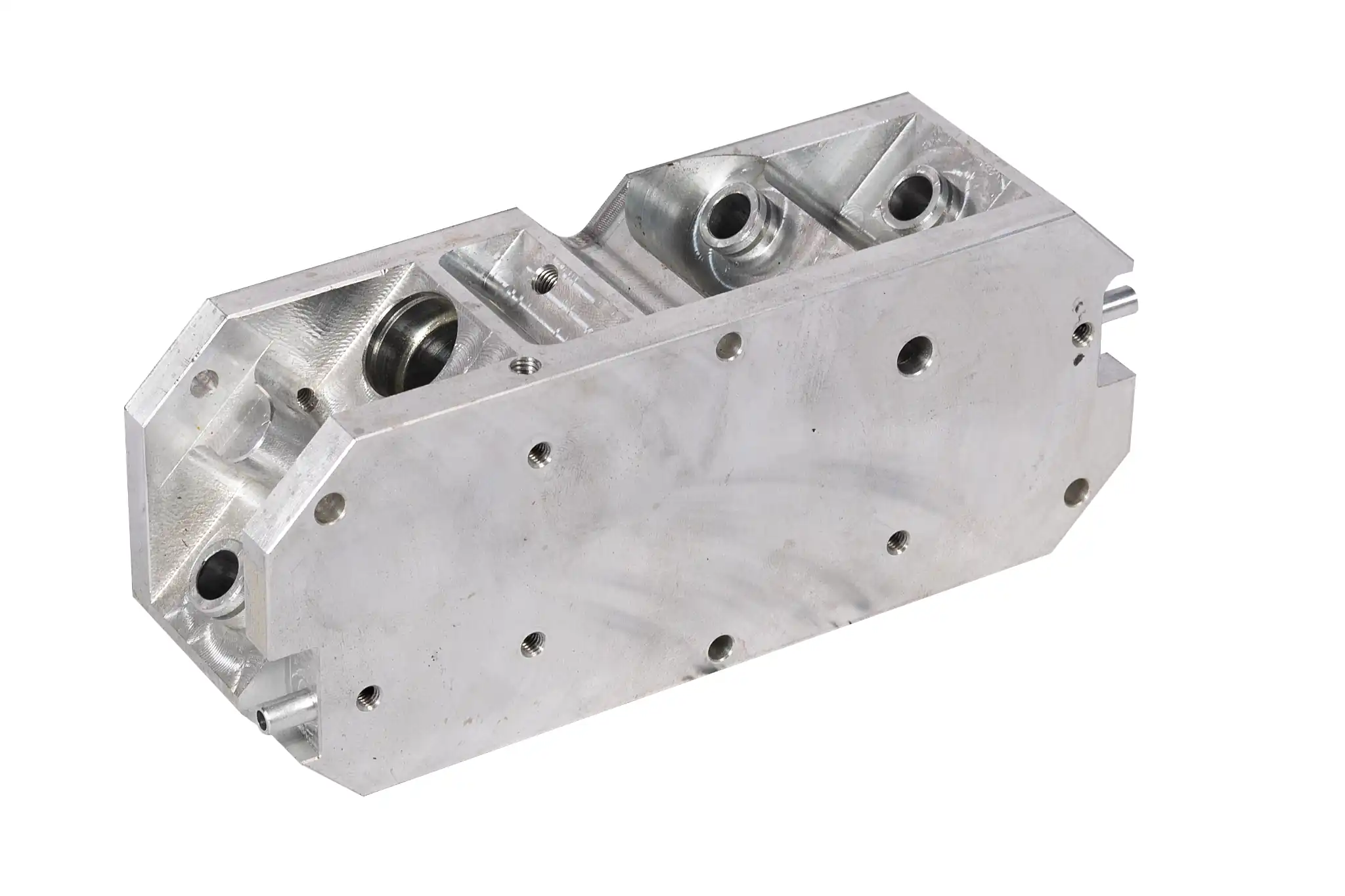
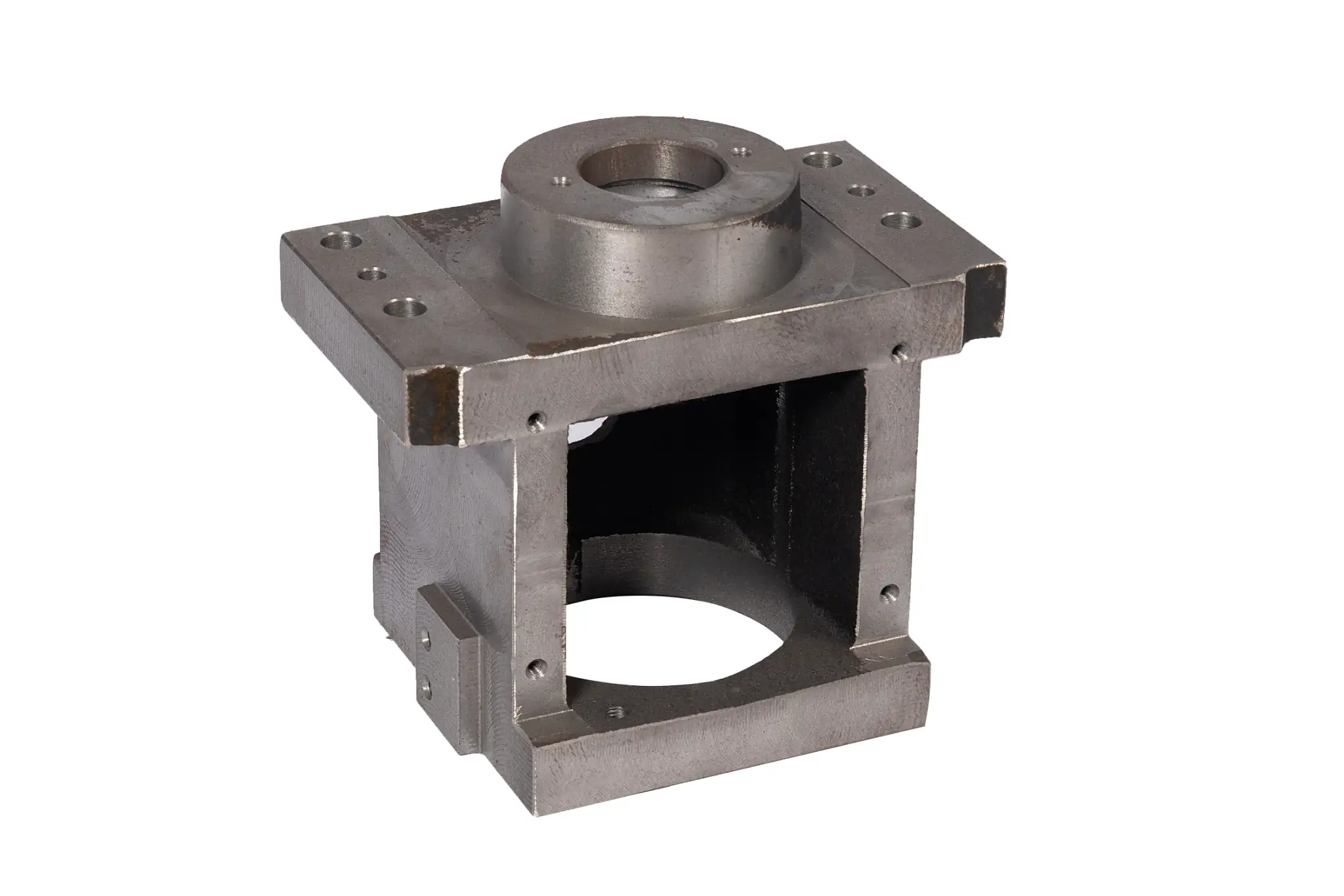
It is critical to distinguish between raw casting tolerances and final machined tolerances. A common design error is expecting as-cast surfaces to meet the precision of CNC machining. Features such as bearing bores, sealing faces, threaded holes, and mounting surfaces require secondary machining to achieve the necessary assembly fit.
By separating as-cast dimensions (for general structure) and machined dimensions (for critical interfaces) in your project planning, you avoid over-tightening requirements on non-functional surfaces, which may increase tooling, inspection, scrap, and machining costs.
| Feature | Usually | Tolerance Consideration |
| Outer profile | As-Cast | Follows standard casting grades. |
| Rib thickness | As-Cast | Influenced by mold flow and draft. |
| Bearing bore | Machined | Requires tight tolerance; plan for allowance. |
| Sealing face | Machined | Flatness and finish are critical. |
| Threaded hole | Machined | Requires CNC drilling/tapping post-cast. |
| Mounting surface | Machined | Critical for assembly fit. |
| Datum surface | Machined | Essential for alignment and stability. |
How to Improve Aluminum Casting Tolerance Control
Define critical areas: Clearly identify which surfaces function as assembly interfaces versus those that only serve as structural profiles.
Plan machining allowances: Ensure 1–2mm of additional material is included on surfaces requiring CNC finish to guarantee clean-up.
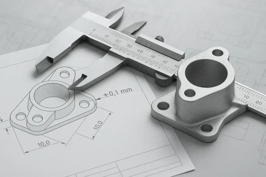
Establish clear datums: Use consistent datum references on your 2D drawing that match your assembly and inspection setup.
Optimize early: Review wall thickness, ribs, bosses, and draft angles during the design phase to minimize thermal distortion.
Align process with requirements: Select the casting process based on the required precision, annual volume, and geometric complexity.
Validate inspection methods: Confirm the measurement approach (e.g., CMM, gauge) with your supplier before production begins.
Common Aluminum Casting Tolerance Standards
Casting tolerances are typically managed through established standards or drawing systems rather than a single fixed number. Different regions and customers utilize varying systems, and these standards should be discussed and confirmed before tooling begins. If a drawing references general tolerances without specifying a casting-specific standard, the foundry and customer may interpret requirements differently.
| Standard or Reference | Typical Use | Notes for Aluminum Castings |
| ISO 8062 / 8062-3 | General casting dimensions | Provides established tolerance grades for castings. |
| ISO 2768 | General machining/fabrication | Often misused for as-cast features; use with caution. |
| DIN / EN Standards | European casting specs | Often specific to the alloy and casting process. |
| Foundry Table | Process-specific capability | Reflects the actual historical capability of the foundry. |
| Customer Standard | Proprietary requirements | Overrides general standards for specific functional parts. |
How to Read an Aluminum Casting Tolerance Table
A tolerance table is not simply a list of numbers; it provides a framework for defining quality. Engineers should verify whether the table applies to raw as-cast surfaces, machined features, or both. Tolerance values for outer profiles do not automatically apply to bearing bores or sealing faces. For critical features, table data must be reviewed alongside your specific machining and inspection plan.
| Table Item | What It Means | Why It Matters |
| Dimension range | The size span of the feature | Larger features often require wider tolerances. |
| Tolerance grade | The precision class assigned | Defines the expected strictness of the fit. |
| Casting process | The method used to form the part | Directly dictates the base capability level. |
| Condition | As-cast or machined | Prevents confusion between raw and finished states. |
| Datum reference | The origin point for measurement | Ensures consistent inspection results. |
| Machining allowance | Extra material for finishing | Prevents insufficient material for CNC clean-up. |
Common Mistakes When Specifying Aluminum Casting Tolerances
Applying CNC tolerances to all as-cast surfaces: Demanding high precision on raw surfaces drives up tooling and scrap costs unnecessarily.
Ignoring draft angle and parting line: Failing to account for these during the design stage leads to parts that do not fit inspection fixtures.
Not separating critical and non-critical dimensions: Labeling every dimension as critical prevents the foundry from optimizing production for cost-effectiveness.
Missing machining allowance: Failing to provide enough material for CNC clean-up often results in parts being rejected.
Unclear inspection datum: Failing to define a primary datum on the 2D drawing leads to measurement discrepancies.
Over-tightening non-functional dimensions: Demanding high precision on areas that do not affect assembly adds cost without value.
Not discussing inspection method before production: Misaligned inspection criteria often cause project delays.
Conclusion
Reasonable aluminum casting tolerances come from balancing casting process capability, tolerance standards, part geometry, machining allowance, and inspection method. The goal is not to apply the tightest tolerance everywhere, but to define the right tolerance standard and tolerance level for each functional area.
By working closely with your foundry to define these parameters during the design stage, you can achieve the required functional precision while maintaining cost-effective production. A well-prepared project plan that distinguishes between as-cast and machined requirements serves as the foundation for a successful and trouble-free production run.
Aluminum Casting Tolerance Support from MinHe
For custom aluminum casting projects involving sand casting, gravity casting, low pressure casting, and post-casting CNC machining, our team can help review drawings, identify critical dimensions, separate as-cast and machined features, and suggest a practical tolerance approach before tooling or batch production begins.