Aluminum casting design influences mold structure, metal flow, demolding, shrinkage, hot spots, machining allowance, and dimensional stability. For industrial components like housings, end caps, brackets, pump bodies, and flanges, the design of parting lines, wall thickness, draft, fillets, bosses, ribs, and hole positions typically needs to be considered before tooling begins.
This guide summarizes 10 common design factors to help engineers understand which structural features influence casting formation, mold feasibility, and downstream machining during the design review phase.
What is Aluminum Casting Design?
Aluminum casting design is not just about completing a 3D model; it is about evaluating part functionality, casting processes, mold structures, demolding methods, shrinkage compensation, machining allowances, and inspection requirements together.
During the design phase, it is necessary to distinguish between casting features and machining features. General geometry, ribs, and boss shapes can be considered as raw casting features, while sealing surfaces, mounting faces, locating holes, bearing holes, and threaded holes usually require machining allowances. Casting tolerances and machining tolerances should be set separately to meet assembly requirements.
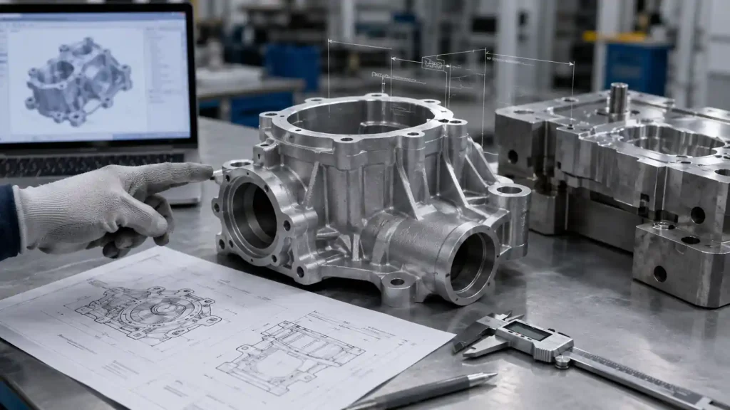
Why Should Aluminum Casting Design be Reviewed Before Tooling?
The value of a pre-tooling review lies in aligning design intent with manufacturing constraints. Issues regarding parting lines, wall thickness, draft, hot spots, undercuts, and hole positions in aluminum castings often appear during trial casting, mold correction, machining, or assembly if not addressed clearly at the drawing stage, thereby increasing modification costs.
From a DFM (Design for Manufacturing) perspective, pre-tooling reviews help confirm which structures are suitable for casting, which locations require subsequent machining, and which areas might involve risks such as hot spots, undercuts, hole-position deviations, or insufficient machining allowance. This allows design drawings, mold schemes, casting blanks, and downstream machining requirements to be aligned earlier.
10 Factors in Aluminum Casting Design
The following 10 factors are common structural and process focus areas in aluminum casting design reviews. They involve alloy selection, mold parting, shrinkage compensation, demolding, wall thickness transitions, localized hot spots, hole design, and downstream machining.
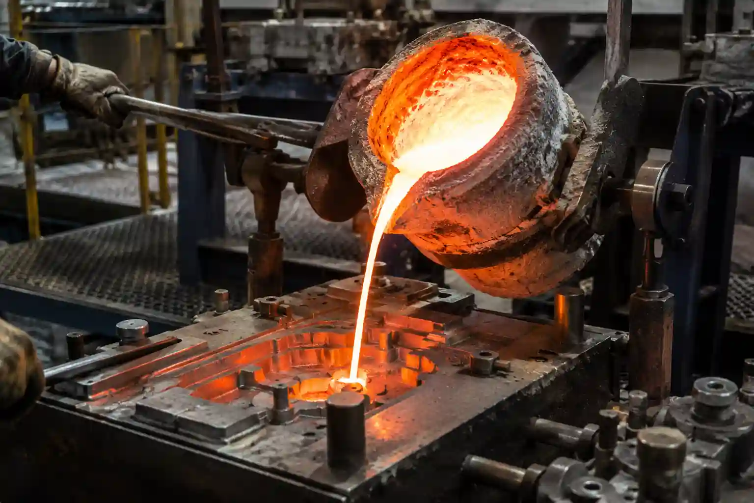
1. Alloy and Process Selection
Different aluminum alloys vary in fluidity, shrinkage behavior, and machinability, which influences the settings for wall thickness, fillets, hole locations, and machining allowances. Design should confirm that the material meets requirements for strength, corrosion resistance, or downstream machining.
Sand casting, gravity/permanent mold casting, low-pressure casting, and die casting processes have different requirements for mold structure, dimensional repeatability, and surface finish. If the process is changed later, parting lines, draft, hole locations, wall thickness, and machining allowances usually require a re-evaluation.
2. Parting Line
The parting line is where the two halves of the mold meet; its design influences flash size, mismatch risk, and cleanup efforts. If the parting line crosses precision sealing surfaces, critical mounting faces, or visible exterior surfaces, it will increase the difficulty of subsequent machining or grinding.
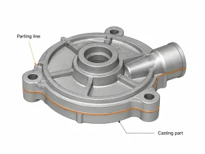
During the drawing review phase, the parting line position should be determined by considering the opening direction, machining fixture schemes, and inspection datums. For housings or flanges, setting the parting line to avoid critical functional surfaces helps reduce dimensional drift caused by mismatch, thereby lowering the difficulty of processing and clamping.
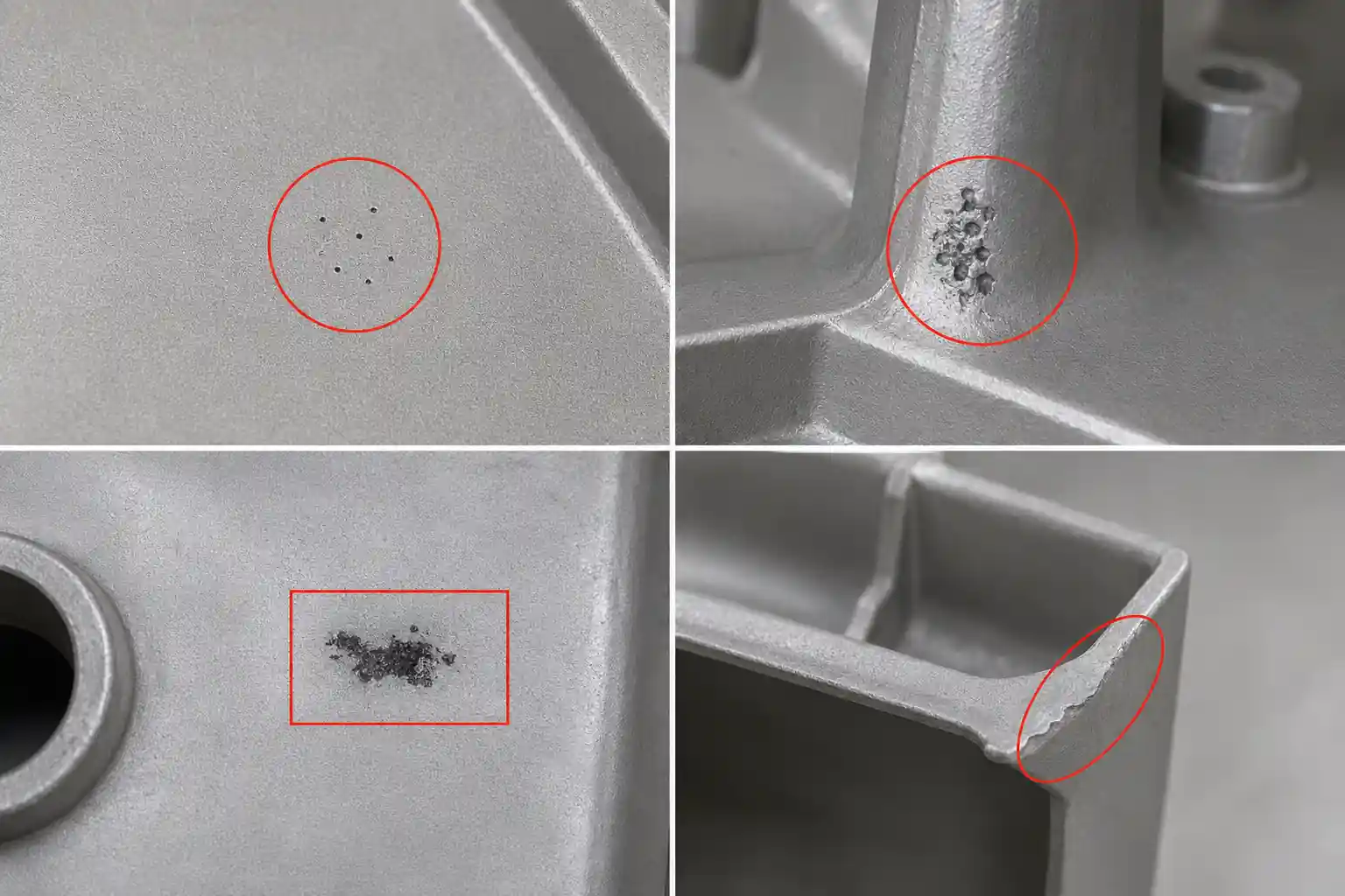
3. Shrinkage Compensation
Aluminum alloys shrink as they solidify and cool. Shrinkage is closely related to thick walls, bosses, intersecting ribs, large flat surfaces, and variations in wall thickness. Thick areas are prone to hot spots, which can lead to shrinkage cavities, porosity, or internal voids.
Before tooling, risks can be reduced by decreasing local solid thickness, adjusting fillets, adding feeding conditions, or optimizing cooling designs. Suppliers typically manage these variations through shrinkage rate settings, mold compensation, and feeding schemes. Dimensional reports after trial casting are used to determine if local mold correction or cooling adjustments are necessary.
4. Draft Angle
The draft angle helps the casting release smoothly from the mold. Draft needs to be considered for outer walls, inner walls, deep cavities, hole walls, ribs, and bosses.
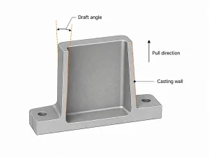
Inner walls, hole walls, and surfaces related to cores are more likely to grip the mold or core due to shrinkage and thus require careful draft settings. Insufficient draft can cause surface scuffing, sticking, ejection deformation, or mold wear. For sealing surfaces, mounting faces, or locating datums, if casting surfaces are not suitable, machining allowance should be reserved for post-process cutting.
5. Wall Thickness
Wall thickness affects filling, cooling, solidification, and shrinkage. Thin walls may lead to incomplete filling, cold shuts, short shots, or edge voids; conversely, thick walls or abrupt changes in thickness may cause hot spots, shrinkage cavities, or porosity.
The design should aim for a uniform wall thickness transition, avoiding abrupt changes. For thick areas, risks can be reduced through coring, weight reduction, fillet transitions, rib reinforcement, or feeding design. Critical machining areas require reasonable allowances, but they should not be made excessively thick to accommodate them.
6. Fillets and Radii
Fillets reduce sharp corners and abrupt transitions, improving metal flow and reducing stress concentration. Proper fillets aid in wall thickness transitions and metal filling, while also reducing local stress.
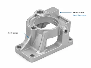
Excessively large fillets can cause local metal accumulation, forming new hot spots. If a right-angle assembly surface is required, it is recommended to reserve machining allowance for post-process cutting rather than relying entirely on casting to form sharp corner features.
7. Bosses
Bosses are commonly used for mounting holes, threaded holes, bearing seats, and locating structures. If designed as large solid blocks, they are prone to localized hot spots, affecting dimensional stability.
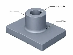
Designers should check the thickness of the base of the boss to avoid excessive solid volume for mounting strength. The center of a boss can be designed with a cast-in hole or an allowance for later machining to reduce metal accumulation. Boss bases should use fillet transitions and consider draft angles. Threaded holes, locating holes, and bearing holes are usually easier to control when machined post-casting.
8. Ribs
Ribs enhance rigidity and support weak areas, but they are not a method for simply thickening the main wall. Ribs that are too thick or intersect at a single point are prone to hot spots, leading to feeding difficulties.
Rib roots require fillet transitions, and the ribs themselves must consider draft angles. Compared to a single thick rib, ribs of moderate thickness that are reasonably distributed are easier to control during metal filling and cooling, and are less likely to cause local thickening.
9. Undercuts
Undercut structures increase mold complexity and may require slides, cores, sand inserts, metal cores, or combined mold structures, depending on the process and part shape.
The design phase should determine if the undercut is necessary. If it can be avoided by adjusting the opening direction, hole orientation, or parting line, simplifying the structure should be prioritized. Simplifying undercuts generally helps reduce mold maintenance difficulty and lowers the risk of dimensional fluctuations caused by moving mold components.
10. Holes and Windows
Holes, windows, long slots, and openings affect metal flow, mold strength, demolding direction, and local cross-sectional strength. If a hole or window is too close to the edge, or the distance between holes is too small, the local structural integrity will be weakened.
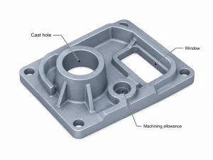
Locating holes, bearing holes, threaded holes, and sealing holes are generally not recommended to rely solely on cast-in dimensions. Cast-in holes, pre-cored holes, or solid bosses can be designed for later machining to meet requirements. For housings or pump bodies, it is necessary to consider core positioning, machining datums, inspection datums, and machining allowances to make the final dimensions, hole-position accuracy, and assembly requirements easier to control during downstream processing.
Conclusion
Aluminum casting design requires evaluating part functionality, casting processes, and downstream machining together. Factors such as alloys, parting lines, shrinkage, draft, wall thickness, fillets, bosses, ribs, undercuts, and hole/window placement all influence mold structure, filling, demolding, hot spots, dimensional stability, and machining allowances.
If you are developing aluminum housings, end caps, brackets, pump bodies, flanges, or other custom castings, MinHe Foundry can review your drawing or 3D file before tooling begins. We can help identify DFM risks related to parting lines, thick sections, draft, undercuts, hole positions, and machining allowances, reducing the likelihood of these issues appearing only during the trial casting or mold correction stages.