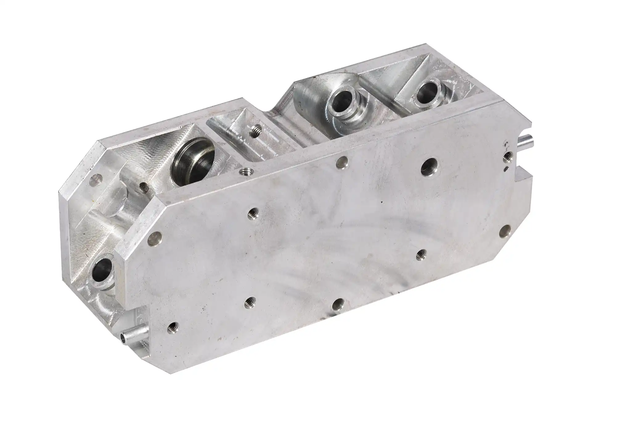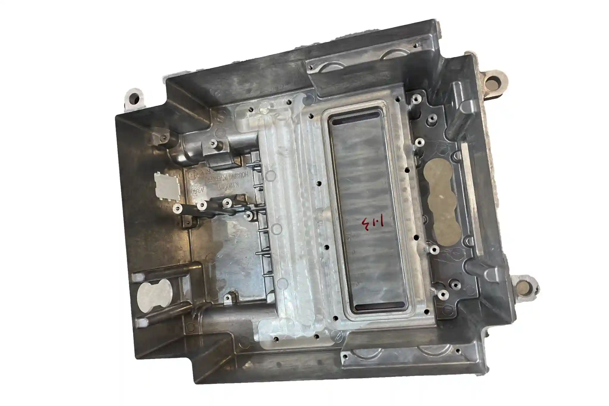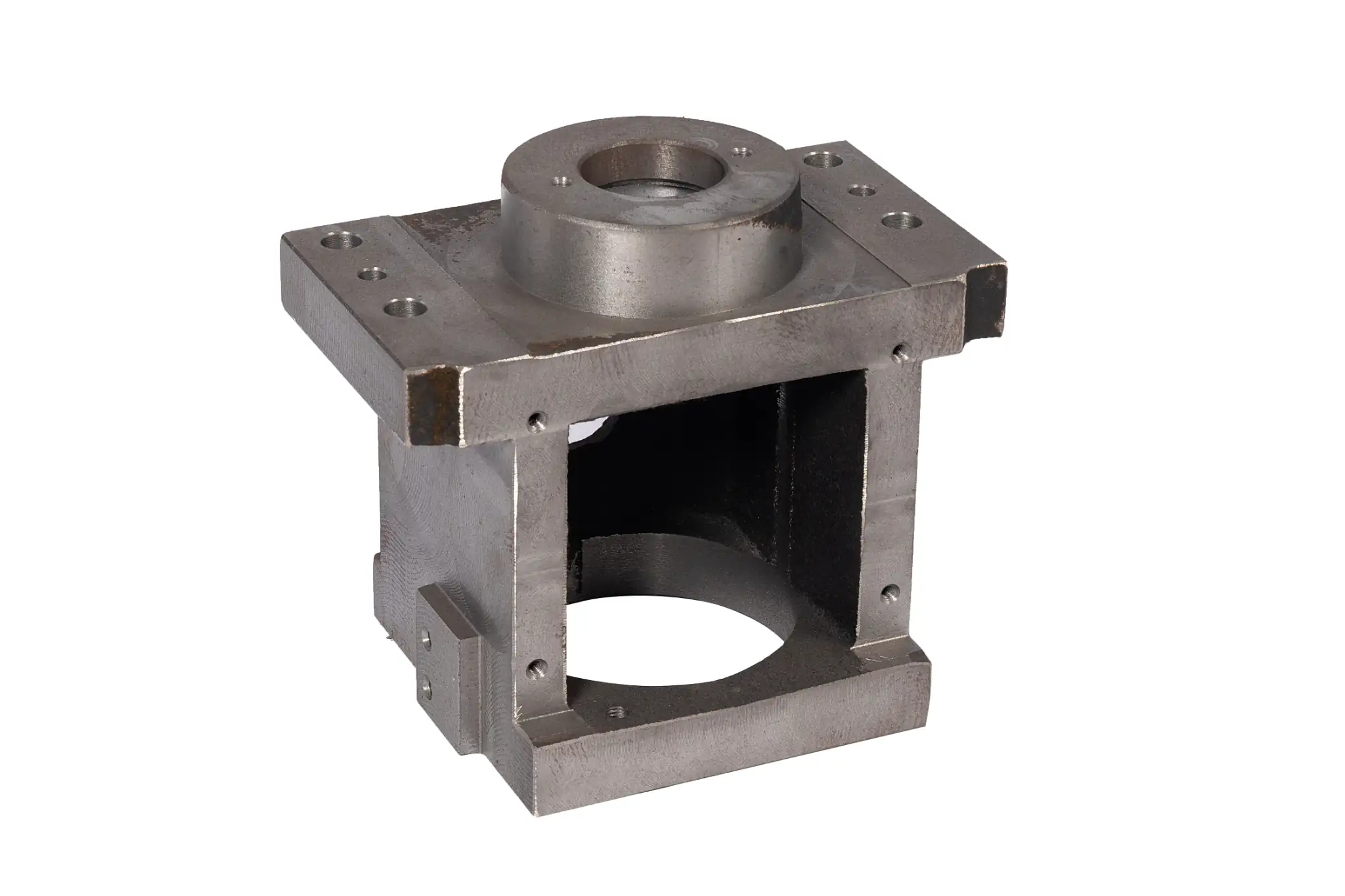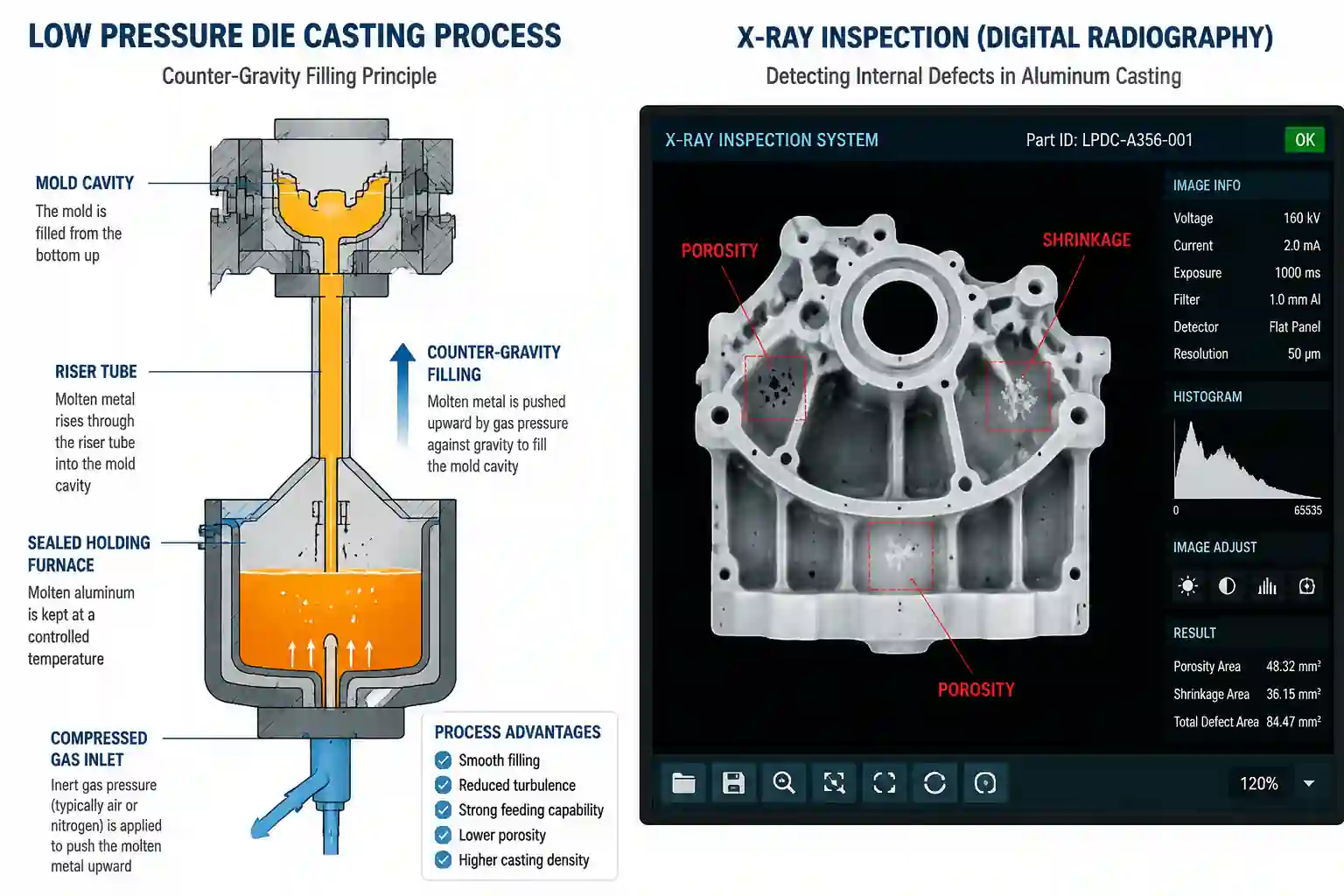



During high-pressure die casting (HPDC) of aluminum, zinc, or magnesium alloys, freshly cast parts often exit the die with a thin rim of excess metal along the parting line. This material is known as die casting flash. Flash is an inherent byproduct of high-pressure casting processes. In typical manufacturing setups, minor, paper-thin flash is considered a normal condition addressed during standard secondary cleaning rather than a defect that leads to rejection. However, when flash becomes excessively thick or widespread, it typically indicates issues with die alignment, machine clamping tonnage, or process parameter control.
How Flash Forms
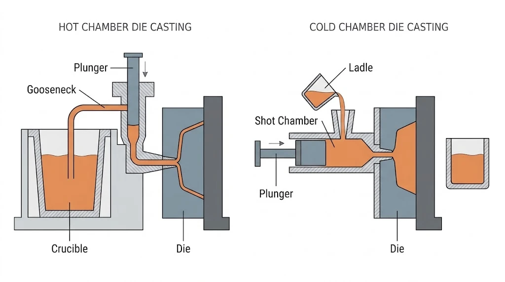
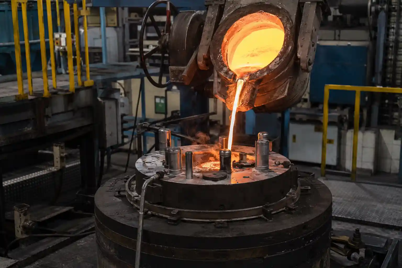
High-pressure die casting involves injecting molten metal into a hardened steel die cavity at high velocity, followed by sustained intensification pressure while the metal solidifies. The die assembly consists of fixed and moving halves, alongside moving components like slides, cores, and ejector pins. Small mechanical running clearances exist between these mating components.
Near the end of cavity fill, intensification pressure reaches several dozen to over a hundred megapascals. If the resulting hydraulic pushout force briefly exceeds the die’s local clamping resistance or contact pressure, molten metal penetrates the parting line, slide guides, or ejector clearances. As this metal solidifies, it forms flash.
Common Locations for Flash
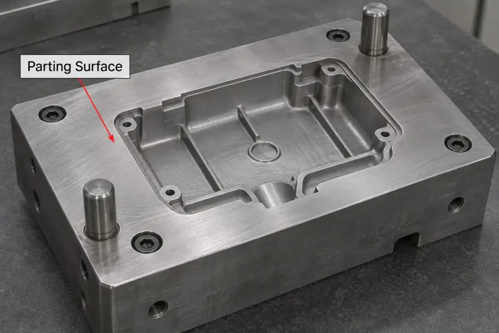
- Main Parting Line: The mating surface between the stationary and moving die halves. If clamping rigidity is insufficient, minor die separation creates a thin sheet of metal along the parting profile.
- Moving Mechanism Interfaces: Sliding tracks and clearance zones between lateral slides/cores and main die inserts.
- Ejection and Insert Perimeters: Clearances around ejector pins, as well as the assembly seams between modular cavity inserts.
Key Factors Behind Excessive Flash
Flash thickness and spread depend on die condition, machine capacity, and injection parameters. Deviations across these areas cause light, manageable flash to become heavy and problematic.
Clamping Force and Machine Sizing
Insufficient clamping force or an oversized total projected area is a primary mechanical cause of heavy flash. Die casting machines use hydraulic and toggle systems to clamp the die shut against internal hydraulic pushout forces. If the combined projected area of the part, runners, and overflows exceeds machine specifications, or if the selected machine tonnage is too low, the die faces can separate slightly during injection, increasing flash thickness.
Die Alignment and Thermal Expansion
Mating surface wear and thermal distortion frequently contribute to flash. Operating under high thermal and mechanical shock, dies can suffer surface denting or damage if trapped metal debris is not cleaned off before closing. In addition, unbalanced cooling channel layouts cause uneven cavity temperatures; the resulting localized thermal expansion prevents the parting line from sealing flush during production.
Injection and Process Parameters
Excessive injection process settings also aggravate flash formation. Switching to the second (fast) injection stage too late or running end-of-stroke speeds too high creates severe hydraulic pressure spikes at the moment of fill. Overly high metal pouring temperatures increase fluidity, making it easier for metal to enter tight clearance gaps. Similarly, applying higher intensification pressure than necessary to meet part density requirements increases the risk of metal leaking into the parting plane.
Practical Effects on Manufacturing
Flash extends beyond cosmetic concerns; it directly impacts production costs, dimensional accuracy, and tooling life.
Post-Processing and Trimming Costs
Heavier flash increases secondary labor and total manufacturing costs. While paper-thin flash shears off readily in a trim die or during shot blasting, thick or awkwardly located flash requires manual deburring, grinding, or filing, which extends cycle times and increases labor input.
Machining and Clamping Accuracy
Incomplete flash removal compromises the accuracy of subsequent precision CNC machining operations. If residual flash remains near primary datum targets, the part cannot seat properly in dedicated machining fixtures. This slight angular or positional misalignment can leave as-cast skin on machined faces or throw critical hole locations off-center.
Die Wear and Parting Line Damage
Detached flash creates a risk of die denting. If hardened metal fragments remain on the parting line without being blown clear, subsequent closing cycles press those fragments directly into the die steel, causing indentations that shorten die life and accelerate flash formation.
Common Control and Removal Methods
Completely eliminating flash in high-pressure die casting is neither technically practical nor cost-effective. The engineering objective is to maintain flash within an easily manageable thickness range through preventive process control and standard secondary finishing operations.
Preventive process control focuses on tooling maintenance and parameter discipline:
- Regular Tooling Maintenance: Regularly inspect and spot-grind parting faces to maintain contact seal, and blow down parting lines with high-pressure air before spraying lubricant to prevent debris buildup.
- Process Parameter Matching: Calibrate deceleration timing and intensification delay, maintain tight control over alloy melt temperatures, and set the first-to-second stage switchover point correctly to lower pressure spikes at the end of fill.
Secondary removal methods depend on part geometry, order volume, and edge specifications:
- Trim Dies: The primary method for volume production, using a hydraulic or mechanical trim press with custom trim dies to shear off external and internal parting-line flash in one stroke.
- Vibratory Finishing and Mechanical Deflashing: Suitable for parts with complex profiles or thin sections where trim die blades cannot reach or might cause distortion.
- Thermal Energy Method (TEM) or Cryogenic Deflashing: Used on precision parts with intricate internal cross-holes or strict particulate cleanliness requirements, relying on brief thermal oxidation or cryogenic embrittlement to strip away fine internal flash.
Conclusion
Die casting flash is an expected outcome of high injection pressures acting across mechanical die clearances. By matching machine tonnage to part geometry, maintaining molten metal and intensification pressure within planned limits, and following routine die maintenance, foundries can keep flash thin and predictable. This balance ensures dimensional repeatability while controlling overall manufacturing costs.
Optimize Your Die Casting Design and Production
Addressing parting lines, draft angles, and datum placement during early design for manufacturability (DFM) reviews keeps flash within an easily trimmable thickness and prevents clamping errors during volume CNC machining.
If you are developing new aluminum or zinc high-pressure die castings or looking to optimize an existing part’s tooling and deflashing workflow, our engineering team can review your 2D and 3D files (STEP/IGES) and provide design for manufacturability (DFM) feedback, tooling concepts, and production estimates.
Contact our engineering team: [email protected]