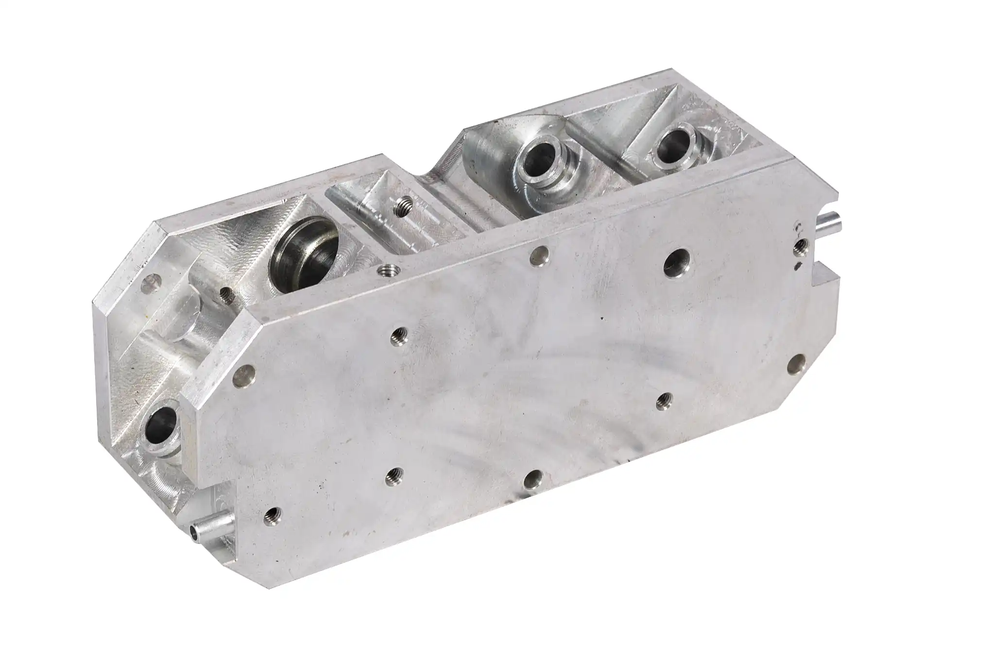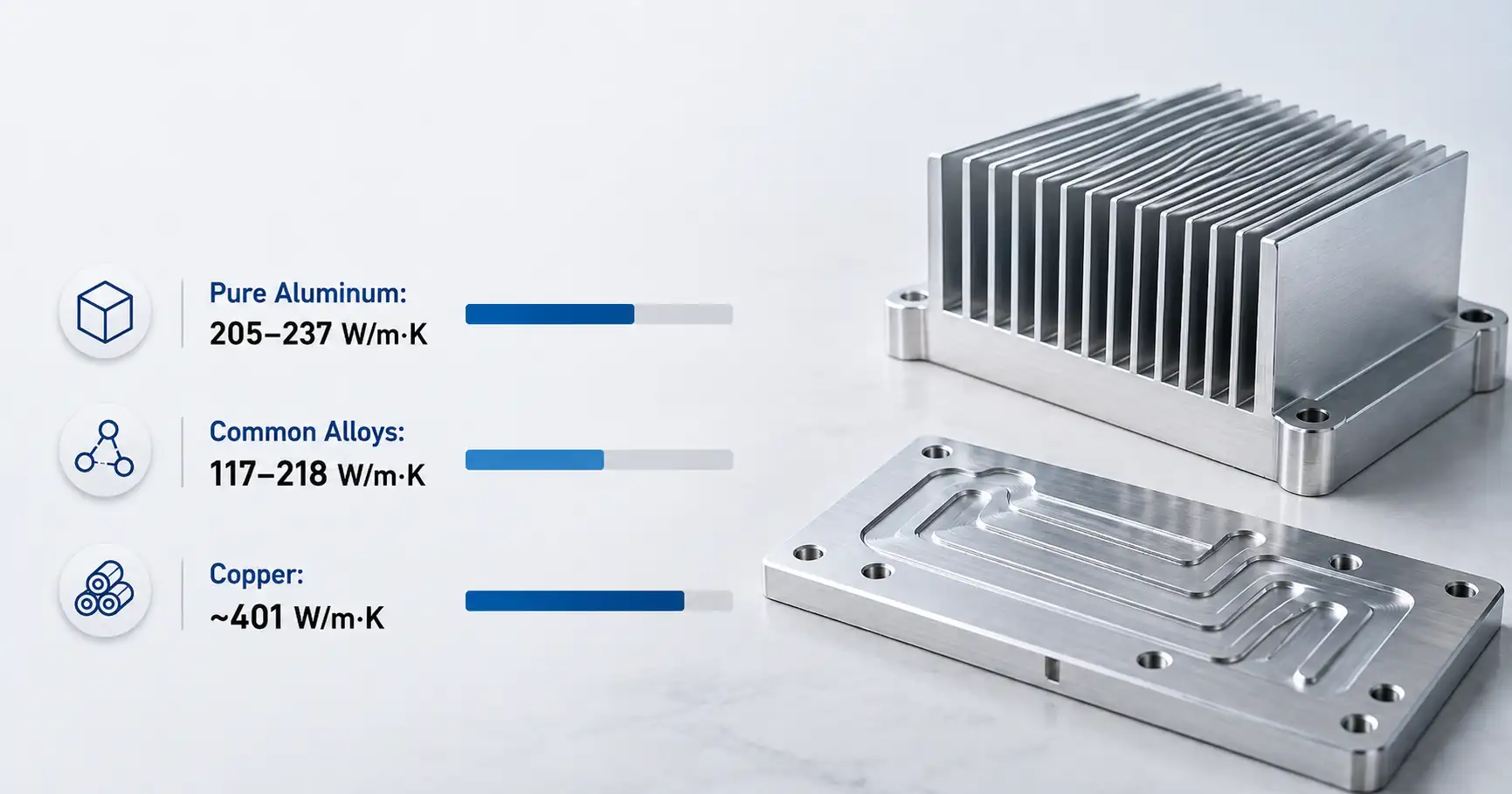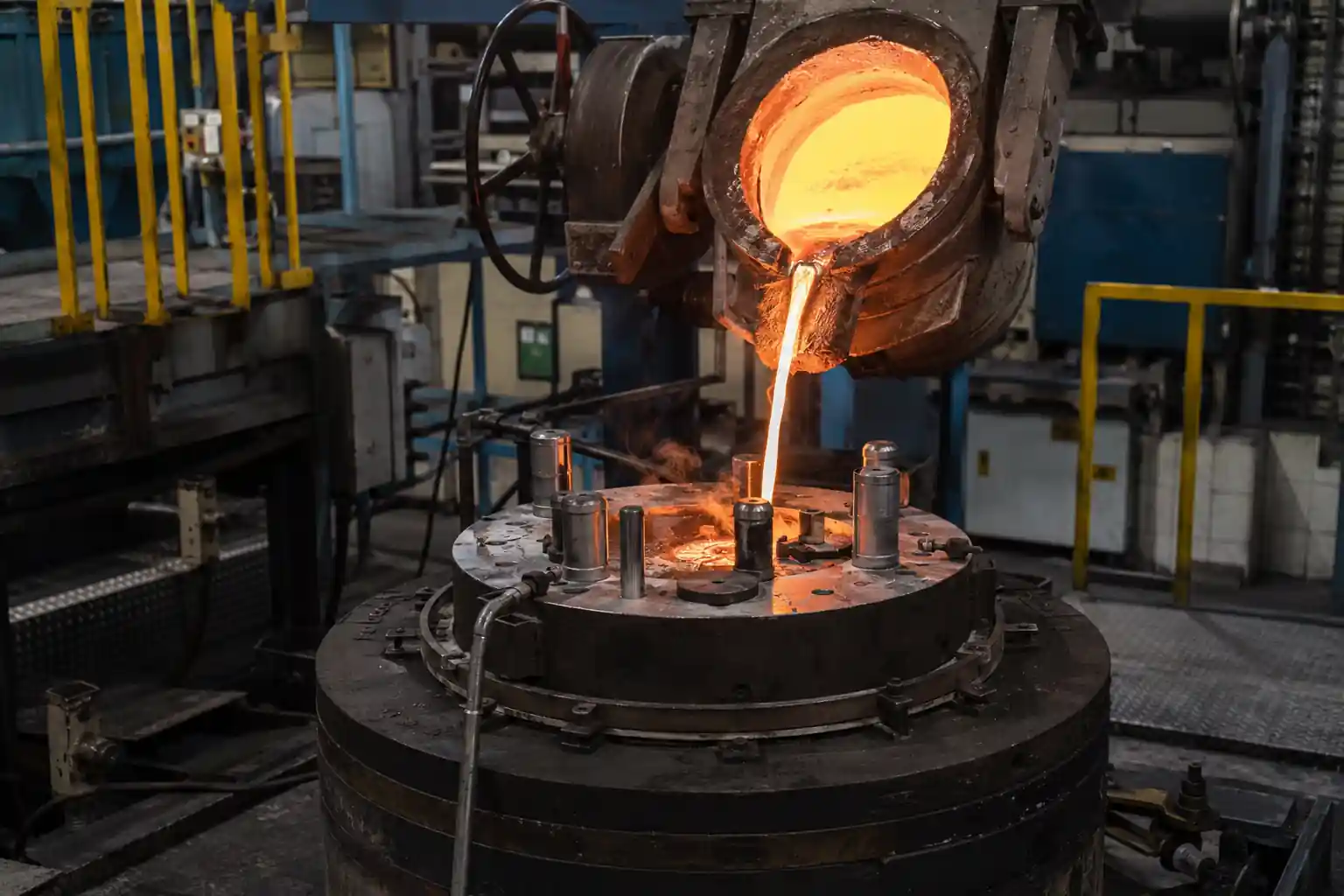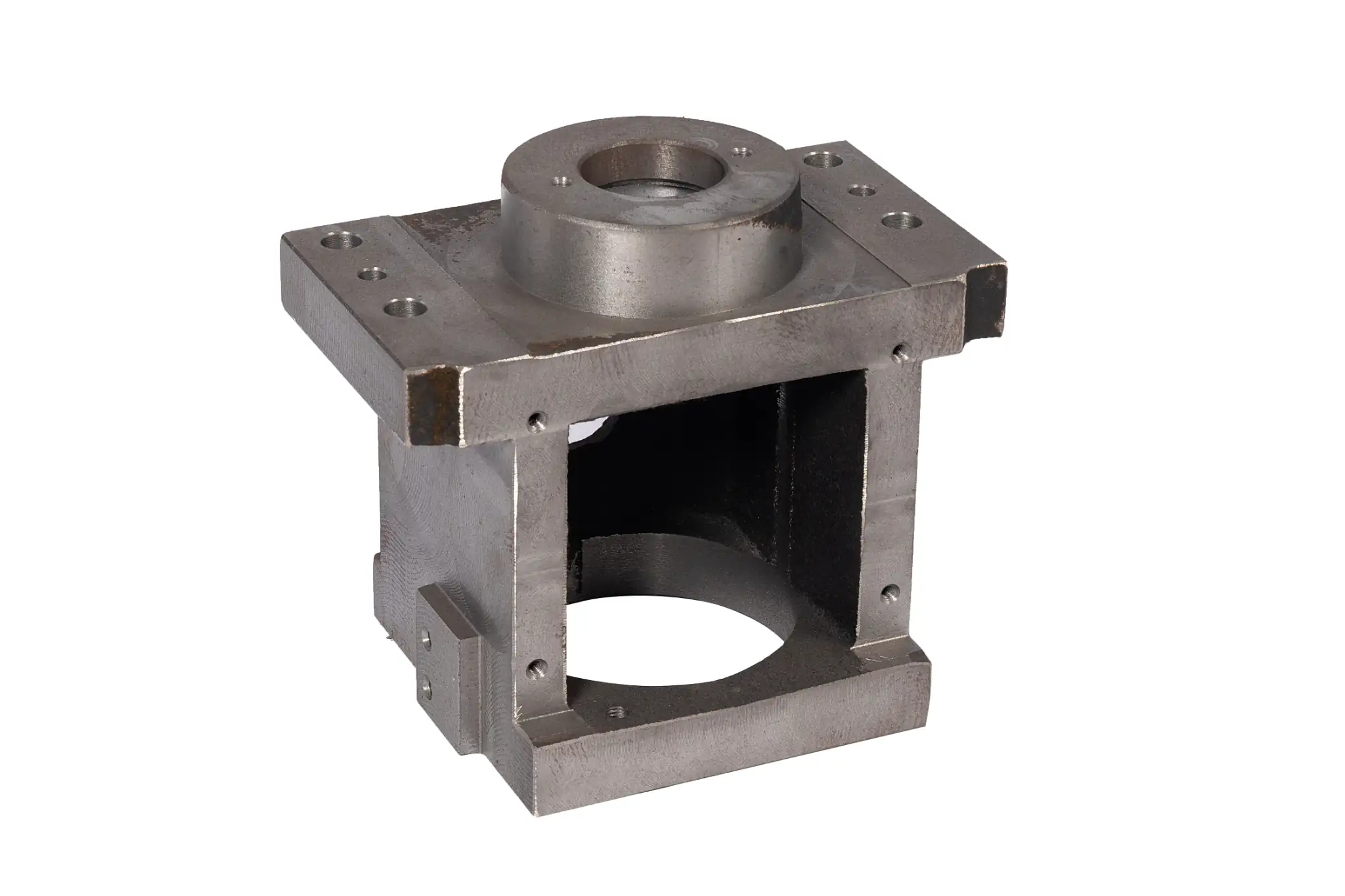



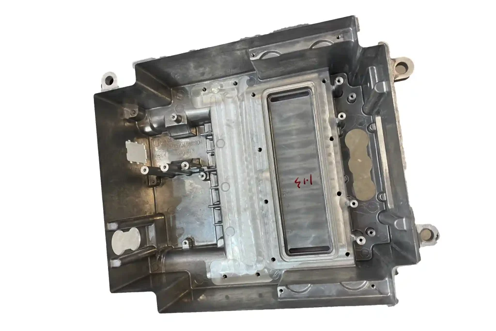
An aluminum motor housing protects the components inside it, supports the motor during installation, and helps remove heat. Two housings may look similar yet pose different manufacturing problems. One has closely spaced cooling fins; another has a thick mounting foot. A liquid-cooled housing also needs internal passages and sealing surfaces that remain sound after machining.
Before choosing an alloy or casting process, look at the features most likely to cause trouble on the drawing. Expected production volume, heat-treatment requirements, and the surfaces that need machining will narrow the options further.
Which aluminum alloy should you use for a motor housing?
Alloy selection and casting process belong in the same discussion. A356 and A357 are candidates for gravity die casting or low-pressure die casting, particularly when the project calls for heat treatment. A380 and ADC12 are common choices for high-pressure die casting and may suit housings with thinner walls or more intricate fins.
That does not make the first pair inherently stronger, or the second pair better at cooling a motor. Compare the required strength, thermal performance, service temperature, surface treatment, and applicable material standard. For a sealed housing, pay particular attention to areas exposed by machining, not just the values on an alloy data sheet. The Aluminum Association’s casting standards and NADCA’s aluminum alloy information are useful starting points for checking grades against casting routes.
If the drawing already specifies an alloy, confirm that it fits the proposed process. If it does not, give the foundry the performance requirements and operating conditions before settling on a grade.
Which casting process fits the housing?
Sand casting, gravity die casting, low-pressure die casting, and high-pressure die casting can all produce aluminum motor housings. They do not solve the same problems. Use the housing geometry and expected volume to shortlist processes, then compare the cost of a finished, inspected part rather than the price of an as-cast blank alone.
Sand casting
Sand casting is worth considering for prototypes, larger housings, and designs that may still change. It generally requires less initial investment in metal tooling, and a design revision is easier to accommodate.
The trade-off often appears downstream. Sand-cast surfaces and dimensional consistency differ from those of metal-mold castings. Stator bores, bearing bores, and mounting faces may need more machining stock. When comparing quotes, include that machining work and the required inspection.
Gravity die casting
Once the design is stable and repeat production is planned, gravity die casting becomes an option. Molten metal enters a reusable metal mold under its own weight. Sand cores can be considered where the housing needs internal features that cannot be released directly from the metal die.
Check the extremes of the drawing first: will the thinnest fins fill reliably, and can the thick mounting areas solidify without unacceptable shrinkage? A metal die removes heat relatively quickly. An adequate average wall thickness does not guarantee that every local feature will fill.
Low-pressure die casting
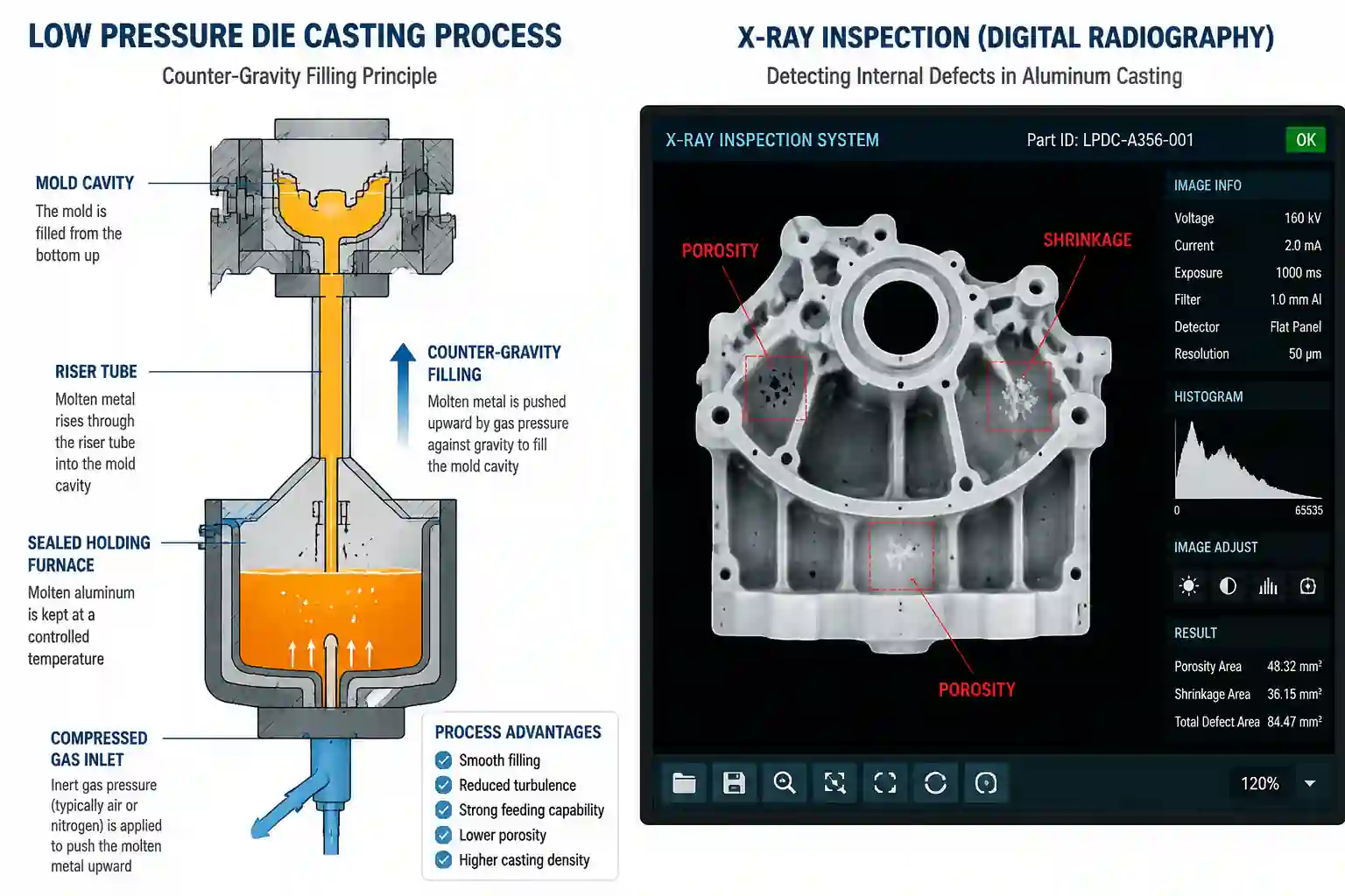
In low-pressure die casting, controlled pressure pushes molten metal upward into the die and can maintain feeding as the casting solidifies. It is worth comparing with gravity die casting when filling and solidification need closer control. The Open University’s process description explains how the metal enters the die.
Low-pressure casting does not, by itself, guarantee a pore-free or leak-tight housing. If machining must not expose porosity near the stator bore, or if coolant passages must seal, define the inspection and leak-test requirements before approving the process.
High-pressure die casting
High-pressure die casting is worth evaluating when production volume is high and the housing has thin walls or detailed fins. Fast filling can form these features efficiently, but the tooling and equipment require a larger initial investment.
Do not judge the process only by whether it can reproduce the outside shape. Thick mounting bosses, deeply machined bearing bores, and liquid-cooling interfaces need a separate review of internal quality. If the drawing calls for heat treatment, confirm that the selected alloy and specific die-casting process can meet the requirement; do not assume the treatment used for a gravity casting will transfer unchanged.
What should you check in the casting design?
A typical housing has a cylindrical body, mounting feet, end flanges, fins, ribs, and a terminal-box boss. Problems often arise where these features meet, rather than in an isolated feature.
| Feature | Design check | Possible problem if overlooked |
|---|---|---|
| Housing wall and transitions | Are wall-thickness changes gradual, and can thin sections fill? | Misruns, uneven cooling, or distortion |
| Cooling fins | Do thickness, spacing, height, and direction suit filling and die release? | Incomplete fins, sticking, or ejection damage |
| Mounting feet, bosses, and rib roots | Do they create isolated heavy sections? Could ribs and fillets improve the transition? | Local shrinkage or unstable dimensions |
| Deep recesses and sidewalls | Is there enough draft for the selected process? | Difficult release or surface damage |
| Machined features | Is machining stock sufficient without being excessive? | Unmachined areas, added machining time, or exposed subsurface porosity |
There is no minimum wall thickness that works for every motor housing. Fin manufacturability also depends on the alloy, flow length, die temperature, gating, and equipment. Ask the foundry to review the thinnest section, the heaviest section, and the critical machined surfaces together.
Before tooling is finalized, review the parting line, gates, vents, and any ejector locations. Keep them away from sealing faces, bearing bores, and specified cosmetic areas where possible. Filling and solidification simulation can help investigate difficult geometry, but trial castings still have to confirm the result.
How do air-cooled and liquid-cooled housings differ?
Some motor heat passes through the contact between the stator and housing before air or coolant carries it away. Alloy conductivity matters, but so do the contact surfaces, housing wall, and cooling geometry.
For an air-cooled housing, check whether airflow actually reaches the fins. Adding more fins or making them taller does not automatically improve cooling. Narrow spacing can restrict airflow while making casting and die release harder. Avoid unnecessary metal buildup at the fin roots as well.
A liquid-cooled housing must satisfy both thermal and sealing requirements. Review passage location, wall thickness around the channels, port connections, and the surfaces that will be machined for seals. A thin channel wall raises concern about leakage; a heavy section around a port may create a local solidification problem.
If a coating could cover a thermal contact surface or grounding point, mark the area that must remain uncoated on the drawing. It is easier to specify masking than to repair a finished housing afterward.
Which features need machining and dimensional control?
Casting forms the main body of the housing. Machining usually establishes the precise relationships needed for assembly. Identify stator bores, bearing bores, end-cover locating features, mounting faces, and sealing faces separately from surfaces that may remain as cast.
The relationship between the stator and bearing bores deserves particular attention. Both bores may meet their individual size tolerances while their alignment remains unsuitable for assembly. Set datums from the way the motor will be located and assembled, rather than specifying each surface in isolation.
Machining stock must cover normal casting variation without adding needless cutting. Too little stock can leave areas unmachined. Removing too much material costs time and may expose subsurface porosity. Thin-walled or asymmetric housings also need a clamping review: a part that measures correctly in the fixture may change shape after it is released.
How should the housing be inspected?
Inspection should follow the housing’s function. A single standard checklist will not suit every design.
Measure critical bores, locating features, and mounting faces against the specified datums. For liquid-cooled or otherwise sealed housings, agree on the test medium, pressure, hold time, and acceptance limit. A drawing note that says only “no leaks” does not give both parties the same inspection criterion.
If internal porosity threatens a loaded area, a deeply machined feature, or a sealing surface, discuss X-ray inspection, sectioning, or another suitable method during development. Automotive projects that require PPAP documentation should define the submission requirements at the start, not after first articles have been cast.
The first production samples need to prove more than castability. They should show that casting, machining, and inspection can meet the drawing together.
What should you send to a foundry for a quote?
Send the 2D drawing and 3D model, along with the expected volume and operating conditions. State whether the housing is air-cooled or liquid-cooled, whether the alloy or heat treatment is fixed, and which surfaces must be machined. Include critical dimensions and any pressure-test or special inspection requirements.
If the design is still open, point out the features you are most concerned about: a thin fin, a heavy mounting foot, or a coolant port, for example. That gives the foundry a useful place to begin its review.
Minhe Foundry can discuss sand casting, gravity die casting, and low-pressure die casting routes against the drawing, together with machining and inspection requirements. If you are evaluating a motor housing project, send the drawings and target volume to the Minhe Foundry engineering team. Resolve the difficult features and acceptance criteria before committing to tooling.