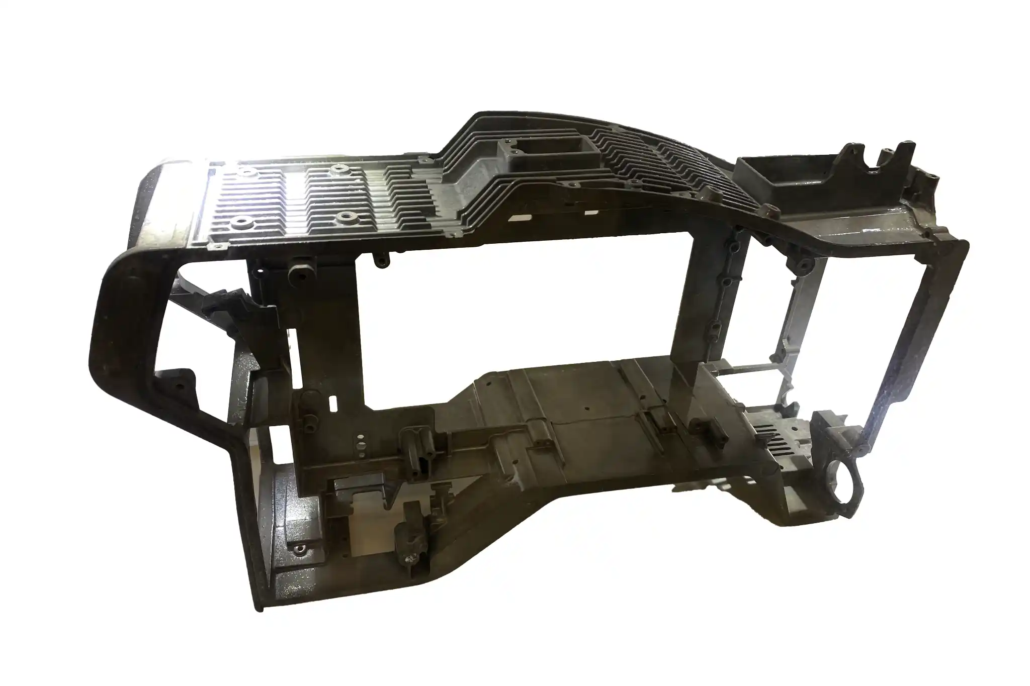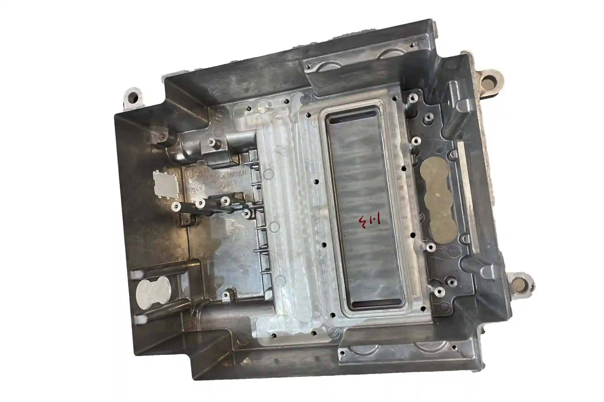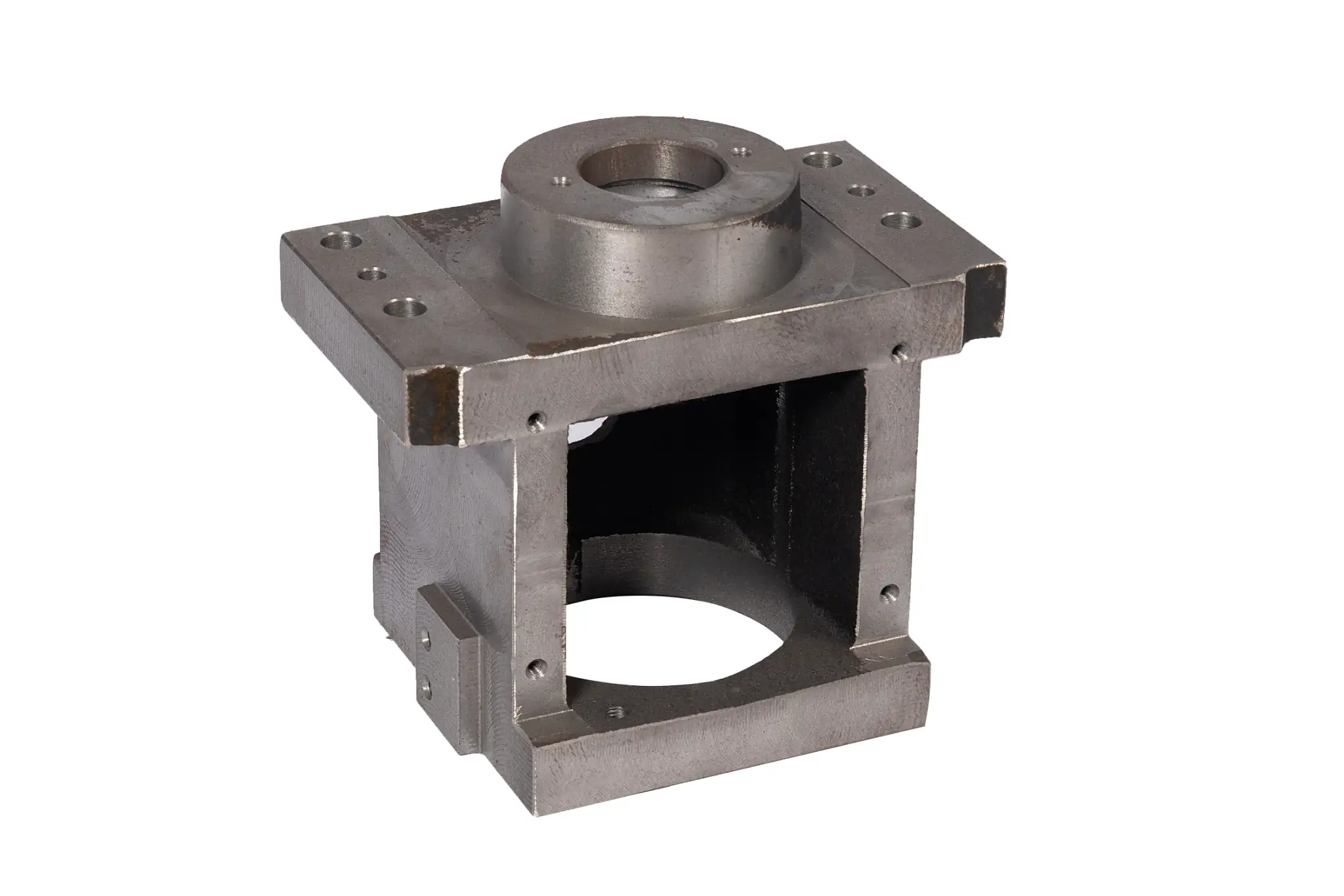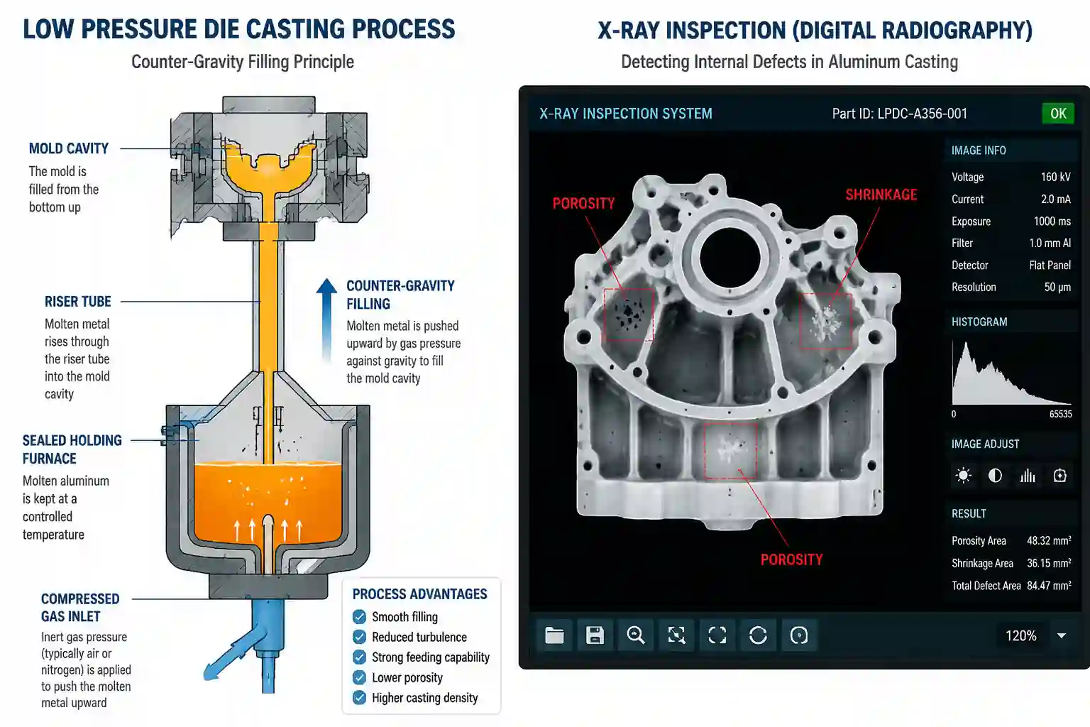



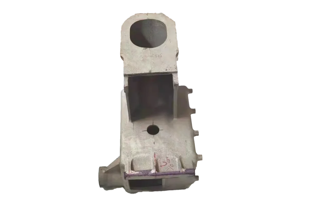
When casting parts transition to machining, extra material is intentionally left behind to accommodate dimensional variations within the allowable blank range and prepare for subsequent cutting. Machining allowances are engineered directly from drawing requirements. They determine whether a blank can be successfully machined to its final dimensions and govern how much material must be removed.
This article explores what machining allowances are, why they matter, the factors that influence them, and the consequences of setting allowances too large or too small.
What is a Casting Machining Allowance?
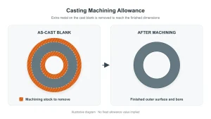
A casting machining allowance is the extra layer of metal intentionally added to mating surfaces, functional surfaces, and other areas of a rough casting that require mechanical processing. This surplus material is completely removed during subsequent turning, milling, or boring operations. Rather than being an arbitrary addition, the allowance is determined by the final dimensions, tolerances, and surface requirements of the product, ensuring there is enough material available for downstream processing.
The Importance of Machining Allowances
- Surface Quality: Machining allowances provide the material needed for subsequent cutting, allowing operators to remove rough as-cast surface layers on machined areas and achieve the surface finish specified in the drawings.
- Dimensions and Shape: Cast blanks experience fluctuations in dimensions and flatness. Appropriate machining allowances enable the blank to undergo shape adjustments through cutting, bringing the features to the required dimensions. Insufficient allowances can result in local areas failing to clean up during machining.
- Locating Datums: Machining allowances are pre-allocated on surfaces intended to serve as datums. Once the allowance is removed, a functional datum face is formed. During subsequent clamping, this surface coordinates with other locating points to precisely position features such as holes according to the engineering drawings.
Machining Allowance vs. Tolerance
While both machining allowances and tolerances relate to part dimensions, they serve distinct purposes:
- Machining Allowance: Refers to the extra material pre-allocated on the surfaces of a casting blank to be removed by subsequent cutting, clearing away as-cast surface layers to reach the final required dimensions and surface finish.
- Finished Dimension Tolerance: Refers to the allowable range of variation specified by the drawing, used to judge whether a machined dimension is acceptable.
In short, the allowance answers how much material to leave before machining, while the tolerance answers how much deviation is allowed after machining.
Factors Influencing Machining Allowances
The design of a machining allowance is influenced by multiple practical variables:
Material Properties
Different alloys exhibit distinct shrinkage behaviors and cutting characteristics. Metals with complex shrinkage patterns experience greater dimensional fluctuations upon cooling, requiring base allowances to be tailored to the alloy’s properties.
Additionally, to hedge against various uncertainties in production, allowances are often intentionally widened. If a casting is prone to warpage or suffers from poor batch stability and locating deviations during clamping, engineers typically increase safety allowances to prevent local unmachined spots (such as remaining casting scale) or outright part rejection.
Casting Processes
The forming method directly determines the initial precision of the blank. Traditional sand casting features rough surfaces and wide dimensional variations, requiring larger cutting allowances. Conversely, gravity metal mold casting or low-pressure casting provides high mold precision and excellent stability, yielding cleaner casting surfaces that allow engineers to design much thinner machining allowances.
Casting Structure and Surface Requirements
A part’s geometry and surface specifications directly dictate allowance distribution. Complex structures with deep cavities or cooling ribs are prone to localized warping during cooling. Furthermore, if functional surfaces demand high roughness or structural density, sufficient cutting depth must be reserved to completely eradicate micro-defects in the surface layer.
Tolerance Requirements
The tolerance specifications on the finished drawing form the foundational basis for designing machining allowances. Through multiple mechanical processing steps, as surplus metal layers are progressively removed, the part dimensions gradually converge and ultimately fall within the tolerance band specified in the drawing.
How to Calculate Machining Allowances
In engineering design, a calculation logic that aligns closely with actual workshop practices involves breaking down the total allowance into three components:
$$\text{Total Allowance} = \text{Surface Deviation} + \text{Tool Operation Allowance} + \text{Finishing Buffer}$$
Taking a typical casting design as a practical example:
$$\text{Allowance} = 0.5\text{ mm (rough surface)} + 0.5\text{ mm (tool feed)} + 0.1\text{ mm (finishing buffer)} = 1.1\text{ mm}$$
- Surface Deviation: Accounts for the rough surface skin, decarburization, oxide scale, and micro-defects on the casting.
- Tool Operation Allowance: Absorbs blank warpage, machine fixture locating errors, and feed allowances during rough turning or rough milling.
- Finishing Buffer: Reserved for final finish turning or milling to guarantee ultimate dimensional accuracy and surface finish.
Shop Floor Programming and Process Control Points:
When processing symmetrical features like internal bores or shaft diameters, ensure the total allowance is converted into a single-sided value when writing G-code. This ensures the CNC machine applies the correct offset to each feature, especially when dealing with stringent tolerance requirements.
Furthermore, machining accuracy relies on more than rigid formulas alone; it requires considering material properties, thermal expansion, and post-heat-treatment distortion. Because tolerance control practices vary across industries, adjustments to processing allowances must be guided by manufacturing constraints and quality control records.
How to Reduce Machining Allowances
In actual production, safely compressing allowances at the design stage to achieve near-net-shape manufacturing relies on optimization across materials, tools, molds, and advanced processing techniques:
- Optimize Material and Tool Matching: Scientifically select tool materials and geometry based on the specific cutting resistance and shrinkage behavior of the alloy, reducing redundant dimensions caused by chatter and tool deflection.
- Strictly Control Sand Mold and Die Quality: Enhance mold rigidity and sand compaction at the foundry end to minimize dimensional scatter caused by mold-wall yield. For instance, applying dedicated anti-adherent coatings or fluorine-based treatment agents to mold cavities prior to sand casting effectively reduces surface burn-on and micro-defects.
- Leverage Multi-Axis Machining Technology: Utilize multi-axis (such as 5-axis) CNC machining to drastically reduce cumulative locating errors caused by multiple repositionings and repeated clamping, allowing engineers to design tighter machining allowances on drawings.
Conclusion & CTA
Machining allowance leaves enough material on the surfaces of a rough casting to meet the drawing’s dimensional and surface requirements. Too little allowance may leave patches of as-cast surface or prevent a feature from reaching its final dimensions; too much increases casting weight and machining time.
To set the allowance, identify which surfaces require machining, then consider dimensional variation in the casting, the casting process, and how the part will be located during machining. First-article measurements and trial machining can show where the allowance can be reduced and where it must be retained.
If you are preparing casting drawings, send the finished dimensions and required machined features to the Minhe team. We can review the casting dimensions and machining scope with you.