


From initial design to final delivery, aluminum sand castings must meet requirements for castability, structural performance, and machining. Wall thickness affects each stage: it influences how molten metal fills the mold, how the casting solidifies, and whether the finished part has sufficient stiffness and machining stock. Selecting a minimum wall thickness therefore starts with a practical reference range, followed by an assessment of the part’s geometry and casting conditions.
Minimum Wall Thickness for Aluminum Sand Casting
A wall thickness of 3–5 mm can serve as an initial design reference for some thin-wall aluminum sand castings. Short sections close to the gate are generally easier to fill. Broad panels and remote thin-wall areas are more demanding and may require greater thickness. The final value also depends on the alloy and pouring conditions.
Part function introduces additional requirements. Load-bearing areas must provide sufficient strength and stiffness, while machined surfaces need additional stock. Hollow housings must also account for possible core shift, which can leave some areas thinner than intended.
Factors Affecting Minimum Wall Thickness
Aluminum Alloy Fluidity and Solidification Characteristics
Molten metal loses heat and begins to solidify as it flows through the sand mold. Differences in alloy composition and solidification behavior affect the ability to fill thin sections.
In a long, thin section, the metal must continue flowing through a narrow cavity. If the flow front loses fluidity too early, the far end may remain unfilled. Changing the alloy can therefore change the wall thickness that can be produced consistently, even when the geometry remains the same.
Material selection also involves strength, corrosion resistance, and heat-treatment requirements. An alloy with good fluidity may not meet every service requirement, so wall thickness design must be based on a defined material specification.
Casting Size and Geometry
Part dimensions influence flow distance, but local geometry is equally important. A short wall and a broad thin panel may have the same thickness, yet the time required for metal to reach every area can differ.
Narrow passages, corners, deep cavities, and abrupt section changes further affect local filling conditions. A thin wall close to the gate may fill early, while an equally thin wall at the far end of the cavity requires the metal to travel farther before reaching it.
Overall part size therefore provides only a rough indication of castability. The wall’s length, area, location, and relationship to the gate give a clearer picture of local filling difficulty.
Sand Mold and Core Conditions
The sand mold must retain the cavity shape during pouring while allowing gases to escape. Sand properties, compaction, and venting conditions all influence local casting quality.
Cored castings are also affected by core position. The outer mold forms the external profile, while the core forms the internal profile. The gap between them determines wall thickness. If the core shifts, the gap decreases on one side and increases on the other, producing uneven walls.
This dimensional variation can remain even when the cavity fills completely. It represents a deviation from the intended geometry and should be distinguished from incomplete filling.
Pouring, Gating, and Feeding Systems
Pouring temperature, filling rate, and gating layout determine the condition of the metal when it reaches a thin section. Gate location and filling direction also influence which areas fill first and last.
Risers primarily supply additional molten metal to compensate for solidification shrinkage. Successfully filling a thin wall does not necessarily mean that an adjacent heavy section will receive adequate feeding. Filling analysis considers whether metal can reach the required areas, while solidification analysis considers whether feeding paths remain open long enough.
Why Wall Thickness Matters
Filling Completeness
When a section is too thin, molten metal may lose fluidity before filling the cavity, causing a misrun. Cold shuts can occur when separate flow fronts meet but fail to fuse properly.
These defects are often location-specific. Remote cavity areas, long narrow walls, and changes in flow direction experience different temperature and flow conditions from areas near the gate. Filling defects may therefore be concentrated in particular regions of the same casting.
Solidification and Internal Quality
Heavy sections generally solidify more slowly than surrounding thin walls and can become local hot spots. The connection between thick and thin sections affects how long feeding paths remain open.
For example, a thin wall connected to a thick boss may solidify and close the feeding path while the boss is still contracting. This can produce shrinkage cavities and porosity inside the boss. Flange roots, mounting seats, and intersections between several ribs can contain similar concentrations of material.
A casting can therefore have every section above its minimum thickness and still develop internal defects because of substantial differences between adjacent sections.
Strength and Dimensional Stability
Wall thickness changes the effective load-bearing section and influences stiffness and deformation. Housing walls, mounting feet, connecting flanges, and bolt bosses perform different functions and do not necessarily require the same section thickness.
Local thickening adds material, but it can also increase cooling differences between adjacent regions. Structural performance and casting quality must be considered within the same geometry. Additional thickness alone does not establish that a design is more reliable.
Material and Machining Costs
Increasing wall thickness raises casting weight. In areas that require cutting, additional material also becomes machining stock, increasing the amount that must be removed.
Excessive thinning, however, may make production more difficult. Trial casting, rework, or scrap can offset material savings. Actual cost depends on material consumption, machining requirements, and production consistency.
Wall Thickness Design for Aluminum Sand Castings
Maintain Uniform Main Wall Sections
Uniform sections help reduce differences in solidification time between regions. Main walls should use similar thicknesses where practical, avoiding abrupt increases or decreases over short distances.
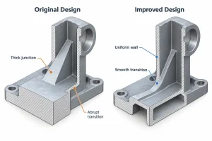
Cross-sectional views are important during design review. A mounting seat or flange connection that appears smooth externally may still contain a substantial concentration of material. Where structural requirements permit, a noncritical heavy region can be hollowed out or reshaped.
Use Gradual Thickness Transitions
When sections of different thicknesses must connect, gradual transitions and suitable fillets can moderate the change. The transition geometry affects both local stress and the volume of material that must solidify.
Larger fillets are not always better. An oversized internal radius can add material at the junction and create another heavy section. The complete cross-section should therefore be examined in relation to the adjoining walls, rather than judging the surface contour alone.
Arrange Ribs and Bosses Carefully
Ribs increase local stiffness, but their roots and intersections also increase section thickness. Several thick ribs meeting at one point can create a concentrated mass of metal.
Rib position, quantity, and connection geometry should follow the load requirements. Bosses must also accommodate connection support, hole machining, and feeding. If a solid boss produces excessive local thickness, a hollow configuration may be considered, together with any additional core-making and machining requirements.
Coordinate Draft Angles and Machining Allowances
Draft changes wall dimensions along the pattern draw direction. For deep cavities and internal walls, the local minimum thickness needs to be checked again after draft has been applied.
The casting machining allowance connects blank dimensions with finished dimensions. Insufficient stock may prevent a surface from cleaning up completely, while excessive stock increases material consumption and cutting requirements. Critical thin sections should be checked against the blank geometry, machining datums, and finished profile to confirm that enough material remains after machining.
Validate Critical Sections
Filling analysis shows how molten metal reaches thin regions, while solidification analysis helps identify hot spots and feeding difficulties. These methods support comparisons between geometry and process options. Actual thickness and quality require sample inspection.
During trial casting, measurements can focus on thin walls, thick-to-thin transitions, and sections surrounding cores. Machined features also require checks of the remaining wall thickness. Internal quality, leak tightness, and structural performance require inspection or testing appropriate to the part’s function.
Clearly specifying nominal thickness, tolerances, and local minimums on the drawing allows validation results to be compared with defined requirements. It also helps establish whether later geometry or process changes have been effective.
Conclusion
Wall thickness in aluminum sand casting depends on alloy characteristics, flow distance, local geometry, and process conditions. For some short thin-wall sections with favorable filling conditions, 3–5 mm can serve as an initial design reference. Uniform walls, gradual transitions, and suitable reinforcing features help address filling and solidification risks, while critical areas require process analysis and sample validation.
If you are developing an aluminum sand casting, share your part drawings, alloy specification, and machining requirements with the MinHe Foundry engineering team. We can help evaluate thin-wall regions, heavy sections, and machining allowances, and provide recommendations for geometry adjustments and casting process selection.