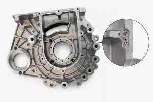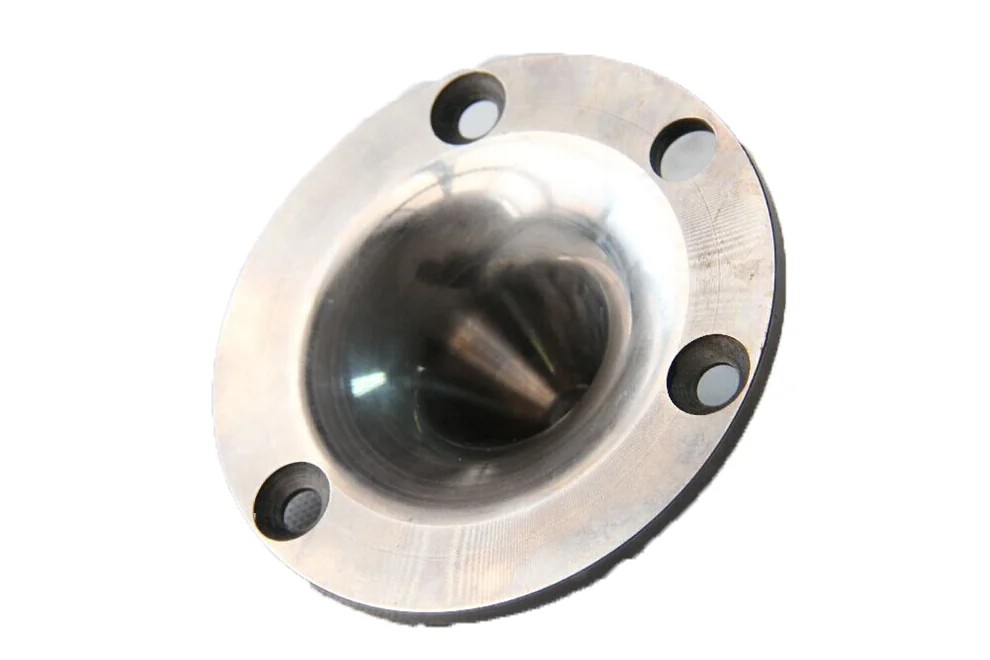
In aluminum casting production, some defects do not appear directly on the as-cast surface. A part may pass visual inspection, but internal voids can be exposed after CNC machining, or leakage may occur during pressure testing. Shrinkage cavities and shrinkage porosity are typical examples of these hidden casting defects.
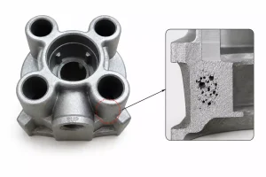
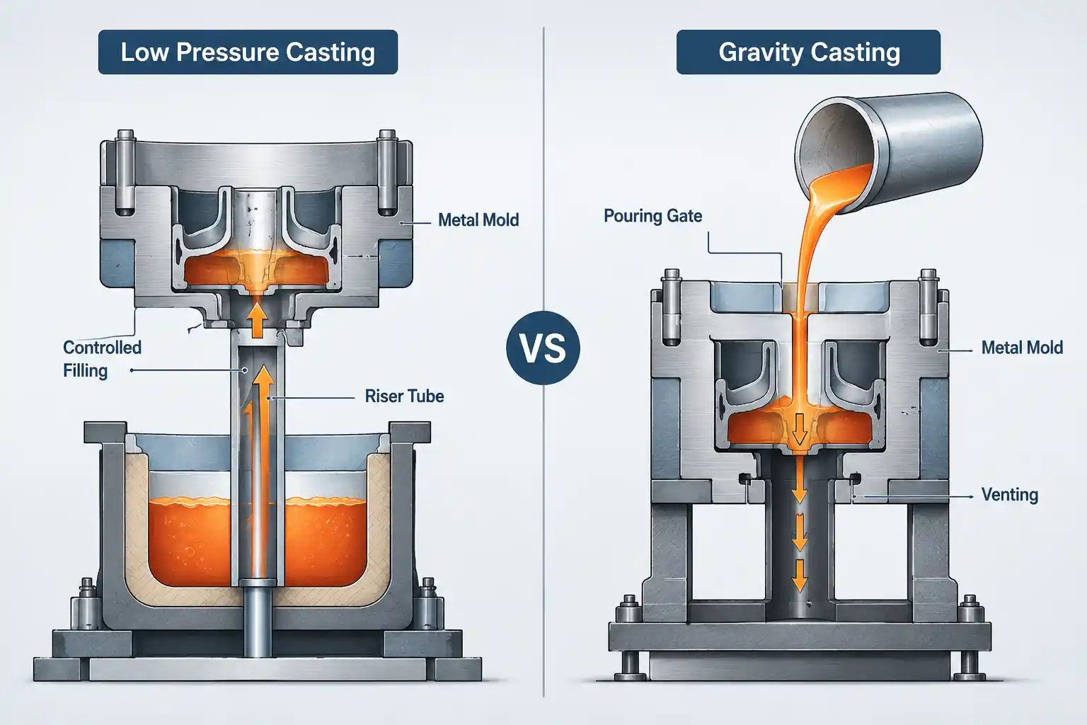
For low pressure casting, gravity die casting, sand casting, and aluminum die cast parts, shrinkage defects may appear in different forms, but the basic mechanism is similar: molten aluminum contracts during solidification without receiving continuous feeding.
This article explains the causes, detection methods, prevention measures, and practical case studies of shrinkage porosity, helping engineers reduce this defect risk in aluminum casting projects.
What Are Shrinkage Cavities and Porosity in Aluminum Casting?
The root cause of shrinkage defects is the volume contraction of aluminum during its solidification phase without sufficient feeding from molten metal.
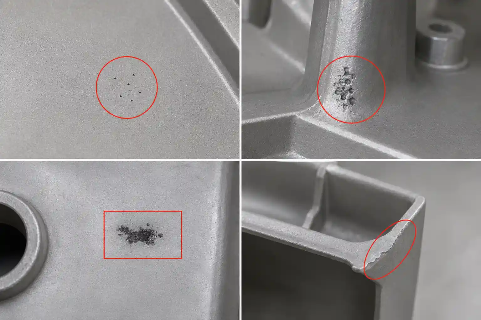
Aluminum alloys typically undergo a volumetric contraction of approximately 4% to 6% when transitioning from liquid to solid. If a specific section of the casting is solidifying while the external feeding paths have already frozen or choked, that section will experience a mass deficit, resulting in rough, irregular internal cavities.
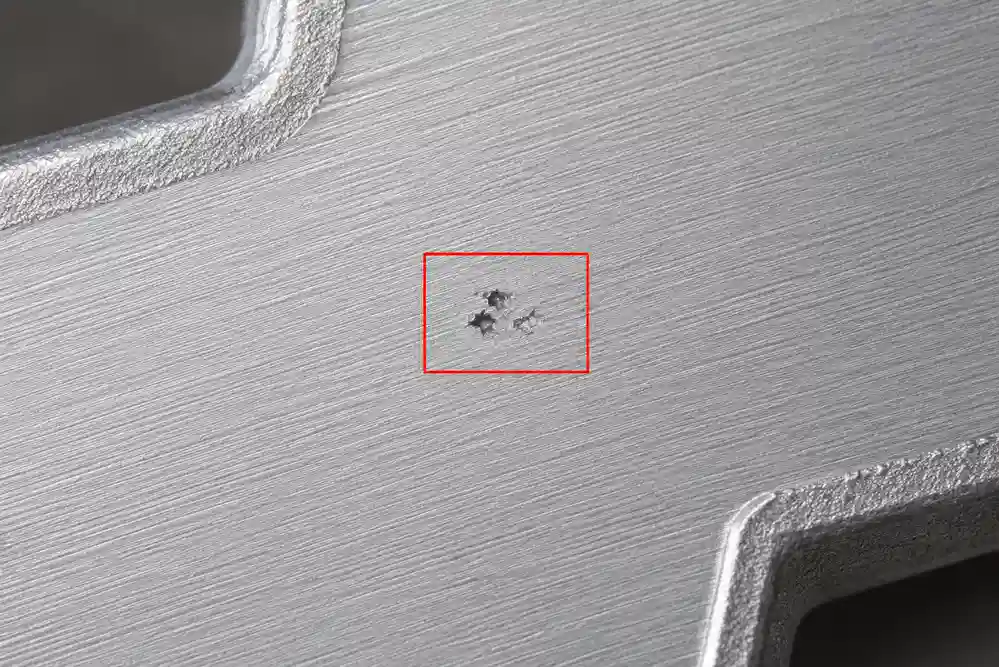
Typical forms of shrinkage defects include shrinkage cavities and shrinkage porosity. Shrinkage cavities usually appear as larger, concentrated voids in thick sections, hot spots, or areas that solidify last, and their internal surfaces are often rough and irregular. Shrinkage porosity is usually finer and more dispersed, often forming between dendritic grains as small interconnected pores or sponge-like voids.
Key Causes of Shrinkage Defects
Shrinkage issues in aluminum castings are rarely caused by a single isolated factor. Instead, they are the collective outcome of part design, mold thermal balance, and process parameters.
Product Structure and Wall Thickness
Areas with thick cross-sections, cross-junctions, or heavy bosses cool down the slowest and are known as “hot spots.” During solidification, thinner sections freeze rapidly due to mold chilling, isolating the thicker sections (hot spots). If the feeding path is prematurely choked, shrinkage cavities or porosity will inevitably form in the center of these hot spots.
Gating and Feeding System Layout
This is the direct trigger for feeding failure. In sand and gravity die casting, it manifests as undersized risers or a premature freezing of the riser neck. In low-pressure die casting (LPDC), it occurs when the holding time is insufficient or the riser tube freezes too early. In high-pressure die casting (HPDC), the relatively thin in-gates often freeze before the intensification phase is complete, cutting off secondary feeding to remote thick sections.
Mold Temperature and Chilling Imbalance
Inadequate cooling line design or localized heat accumulation during continuous production runs can create artificial hot spots. This disrupts the principle of directional solidification, which requires the casting to freeze progressively from the furthest areas back toward the gating/feeding source.
Alloy Composition and Solidification Characteristics
Solidification behavior varies greatly across different aluminum grades. Alloys with wide freezing zones (the temperature gap between liquidus and solidus lines, such as certain Al-Cu or Al-Mg series) tend to undergo a mushy solidification mode. This significantly increases the flow resistance of molten aluminum between dendrites, making feeding extremely difficult and leading to dispersed micro-porosity. Conversely, standard Al-Si alloys (like A356) have better fluidity and a lower tendency for micro-shrinkage when processed correctly.
Common Industrial Inspection Methods
Depending on the production phase and quality control standards, foundries typically utilize a combination of the following Non-Destructive Testing (NDT) and destructive testing methods:
| Inspection Method | Production Phase | Identifiable Issues | Limitations |
| Post-Machining Visual Inspection | Post-Machining | Detects macro-shrinkage exposed on critical sealing faces or threaded holes. | A reactive approach; cannot detect subsurface defects in unmachined areas. |
| X-ray Inspection (RT) | Cast/Finished Part Sampling | Evaluates large internal shrinkage cavities and clustered porosity (2D imaging). | Less sensitive to fine micro-porosity or micro-voids in extremely thin walls. |
| Industrial CT Scanning | Prototyping / Failure Analysis | Provides 3D quantitative analysis of porosity rate, volume, and spatial connectivity. | High equipment costs and long cycle times; impractical for 100% mass production inspection. |
| Airtightness Pressure Testing | 100% Finished Parts | Detects through-wall leaks caused by interconnected porosity (bubble or pressure decay test). | Only identifies whether a leak exists; cannot locate non-penetrating latent shrinkage cavities. |
| Sectioning & Metallographic Analysis | Process Approval / Sampling | Distinguishes between gas porosity, shrinkage, and grain boundaries under a microscope. | Destructive testing; strictly limited to R&D phases or defect root-cause tracing. |
How to Prevent Aluminum Casting Shrinkage Defects?
The core philosophy of eliminating shrinkage is simple: Control the solidification sequence and ensure unobstructed feeding channels.
Product Structural Design
Intervene early during the product design phase to ensure uniform wall thickness wherever possible. For thick mounting bosses, implement core-out designs to reduce mass, adding ribs later to maintain structural rigidity. Use generous fillets and gradual transitions between wall thickness changes to prevent localized heat concentration.
Gating and Feeding Systems
Artificially create a proper temperature gradient to ensure directional solidification. For sand, gravity, and low-pressure casting, adjust the gating positions, use localized cooling water lines, or embed high-thermal-conductivity metal chills on the outer walls of hot spots to force rapid solidification, effectively pushing the shrinkage area into the risers.
For high-pressure die castings with unavoidable local thick walls, deploy squeeze pins (local mechanical intensification) or targeted point-cooling configurations to compress and feed the semi-solidifying metal matrix.
Mold Thermal Balance Control
Utilize mold temperature controllers (TCUs) and precise cooling circuits (such as high-pressure spot cooling) to independently regulate the temperature of core pins and blocks near hot spots. Keeping the mold within a stable target temperature window prevents localized overheating and artificial hot spots from forming.
Melting and Pouring Process Control
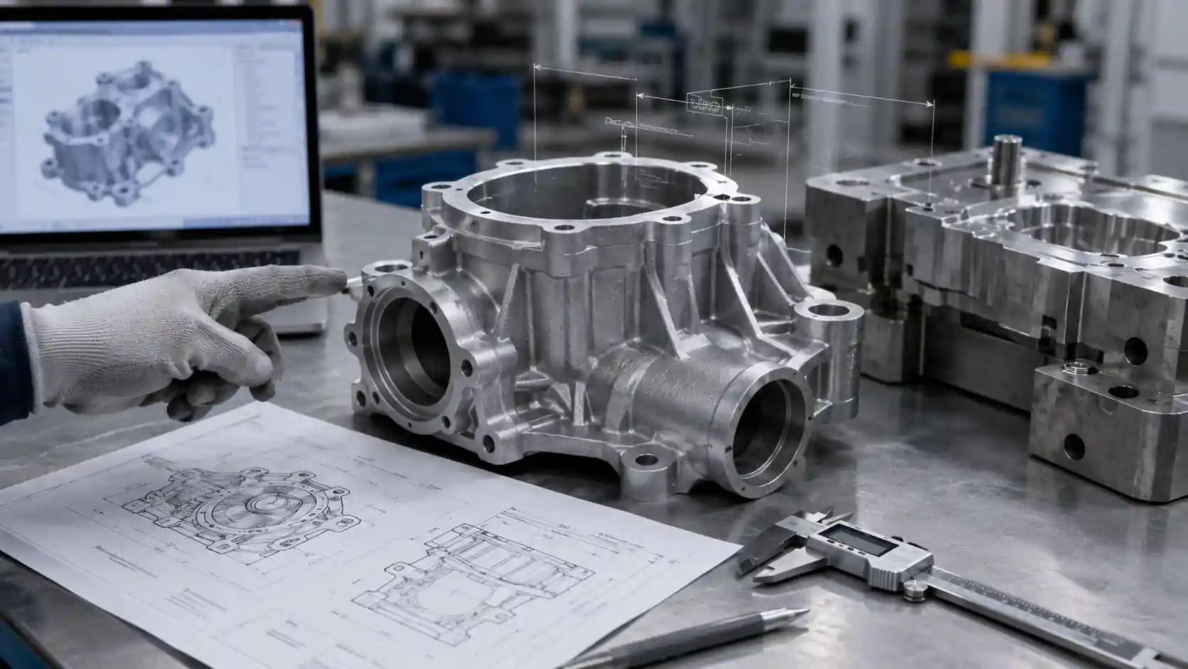
Strictly monitor the pouring temperature. While ensuring complete cavity filling, keep the pouring temperature as low as practically possible to minimize total liquid contraction. Additionally, mandate the use of casting CAE simulation software (e.g., MAGMA, ProCAST) to digitally optimize gating layouts and cooling line placements prior to cutting tool steel.