


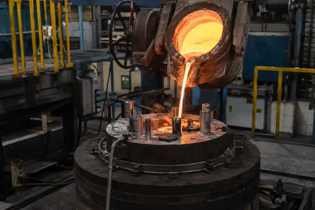
Le moulage sous basse pression (LPDC) utilise une pression d'air comprise entre 0,06 et 0,15 MPa pour propulser l'aluminium fondu vers le haut dans un moule, où il se répand uniformément avant de se solidifier sous pression. Ce procédé convient aux pièces structurelles telles que les sous-châssis et les boîtiers de batterie. Mais quelle que soit la qualité du procédé, une conception inadéquate entraîne toujours la production de pièces défectueuses. Cet article s'adresse aux ingénieurs chargés de la conception de pièces par LPDC : il explique comment définir l’épaisseur des parois, les tolérances et les angles de dépouille, présente les règles de conception propres au LPDC et indique comment éviter la porosité et le retrait dès la phase de conception. Une liste de contrôle de conception est fournie pour faciliter la révision des plans.
Qu'est-ce que le moulage sous pression ?
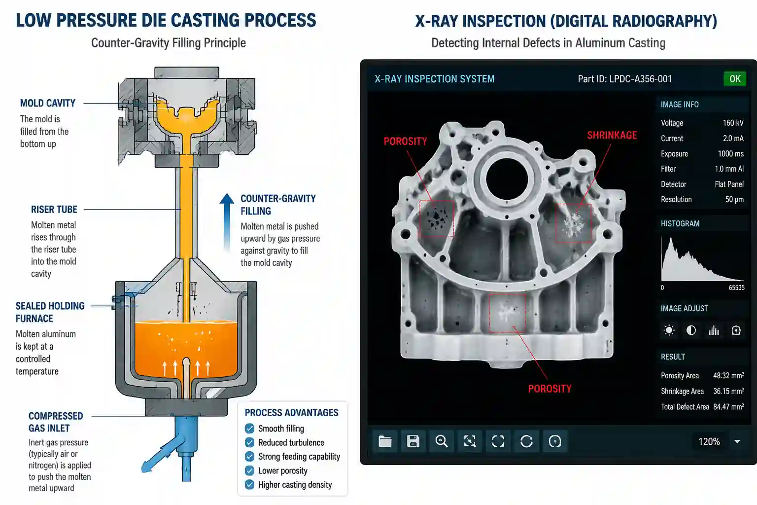
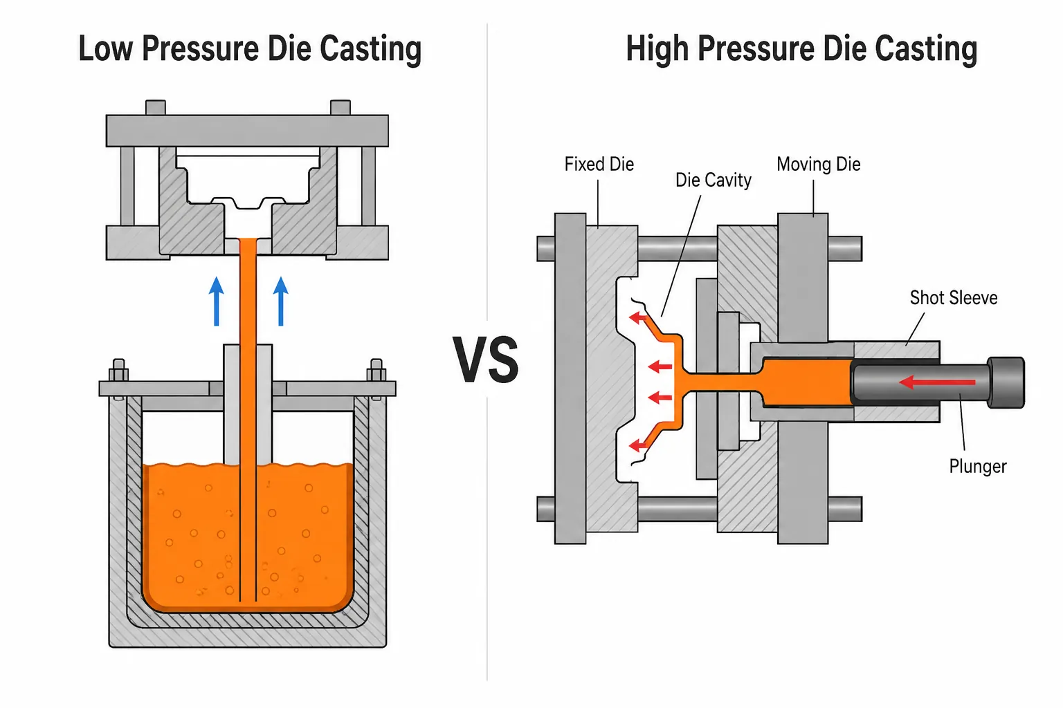
Le moulage sous basse pression consiste à placer le moule au-dessus d'un four étanche, à injecter de l'air comprimé à une pression comprise entre 0,06 et 0,15 MPa, et à propulser le métal le long d'un tube de coulée afin de remplir la cavité sous pression. La principale différence par rapport au moulage sous haute pression réside dans le comportement de remplissage : le moulage sous basse pression (LPDC) permet un remplissage en douceur avec moins d’inclusion de gaz, et les pièces peuvent subir un traitement thermique. Par rapport au moulage par gravité, la pression contrôle la vitesse de remplissage et assure une meilleure alimentation, ce qui confère à la structure une plus grande densité. Le moulage sous basse pression convient aux pièces structurelles en aluminium pour des séries de plusieurs milliers de pièces et plus.
Fonctionnement du moulage sous basse pression
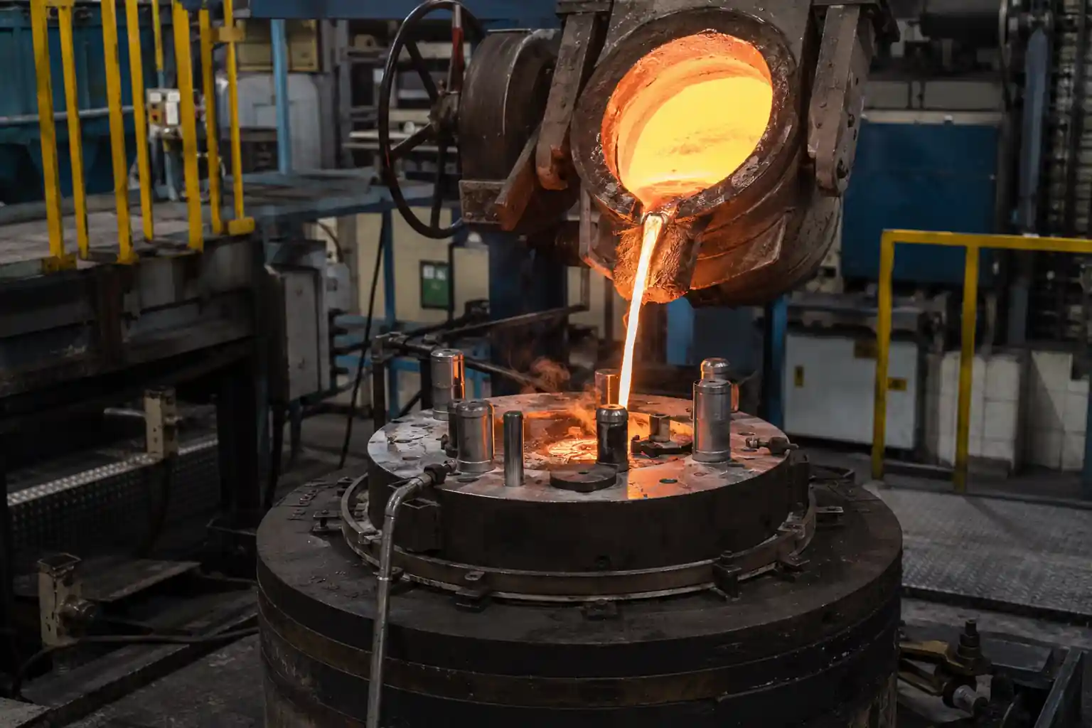
Le cycle LPDC comporte six étapes : fermeture et préchauffage du moule, mise sous pression, remplissage, maintien sous pression pour la solidification, relâchement de la pression et ouverture du moule. Le moule est préchauffé à une température comprise entre 150 et 300 °C ; de l’air comprimé pénètre dans le four hermétique ; le métal remonte par le tube de coulée jusqu’à la cavité ; la pression est maintenue jusqu’à ce que la solidification soit terminée, puis le moule s’ouvre. La courbe de pression et le contrôle de la température du moule déterminent la qualité du remplissage et de l'alimentation tout au long du cycle, ce qui explique pourquoi le procédé LPDC exige un contrôle rigoureux du processus.
Paramètres de conception clés pour les pièces LPDC
| Paramètres | Valeur recommandée | Notes |
|---|---|---|
| Épaisseur de la paroi | ≥ 3 mm, aussi uniforme que possible | Les parois minces résistent au remplissage ; les variations brusques d'épaisseur créent des points chauds |
| Tolérance linéaire | ISO 8062 CT8 | Épaisseur de paroi CT9 ; consulter le tableau pour connaître les dimensions de la pièce |
| Angle de tirage | 1° vers l'extérieur, 2-3° vers l'intérieur, amplitude de 0,5 à 3° | Tenir compte de la profondeur des reliefs et de la texture de la surface |
| Joints de raccordement entre murs | Progressif | Évitez les changements brusques et les sections épaisses isolées afin de réduire le retrait. |
| Coins | En filets | Évitez les angles vifs qui concentrent les contraintes et limitent le remplissage |
| Côtes | Utilisé pour la rigidité | Utilisez des nervures plutôt que des parois plus épaisses pour limiter le poids et éviter les points de surchauffe |
Commencez par l'épaisseur de paroi et l'angle de dépouille, puis vérifiez les transitions et les congés. Une épaisseur de paroi uniforme est la première règle de la conception LPDC : les sections dont l'épaisseur varie brusquement se solidifient à des vitesses différentes et sont souvent sujettes au retrait.
Règles de conception propres à LPDC
C'est surtout par rapport à la haute pression que le LPDC se distingue le plus et le moulage par gravité Dans le sens du remplissage : le métal remonte depuis le fond par le tube de montée. Cela donne lieu à trois règles que vous ne retrouverez pas dans d’autres procédés.
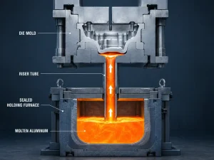
Système d'alimentation par le bas et parcours d'alimentation. Le LPDC doit être rempli par le bas, et la position de la busette définit le trajet d’alimentation à travers le tube de montée. Chaque section épaisse doit se trouver sur ce trajet d’alimentation afin de continuer à recevoir du métal pendant la solidification ; un point chaud situé loin de la busette risque de se rétrécir.
Vérifiez dès que possible les positions des vannes et des colonnes montantes. Le positionnement des canaux de coulée et des montées n'a pas d'équivalent direct dans les autres procédés de moulage, et c'est là que les défauts liés au moulage LPDC trouvent le plus souvent leur origine. Il convient de régler ce point avant de réaliser les outils de découpe, et non après les essais.
Évitez les sections épaisses isolées. Les sections épaisses qui ne peuvent pas être alimentées constituent des zones à risque de retrait. Concevez les sections de manière à ce qu’elles soient raccordées au circuit d’alimentation, ou compensez ce phénomène à l’aide de refroidisseurs et d’un contrôle de la température de la matrice.
Ces trois règles constituent les premiers éléments qu’une fonderie vérifie lorsqu’elle examine les plans LPDC.
Défauts de conception et prévention
Trois défauts concernent principalement les composants LPDC, et la plupart peuvent être évités dès la phase de conception :
- Porosité: les gaz entraînés proviennent d'un remplissage instable ; il faut éviter les parois minces et les sections complexes qui provoquent des turbulences. Les gaz dissous proviennent de la masse fondue et sont contrôlés par le dégazage.
- Rétrécissement: cela est dû à une alimentation insuffisante ; veillez à ce que les parois soient homogènes, évitez les zones de surchauffe isolées et privilégiez l'utilisation de colonnes montantes et d'un système de refroidissement adapté.
- Fermetures à froid: les filets de métal se rejoignent sans se fondre ; évitez les parois trop fines et les longs trajets de coulée, et augmentez la température de coulée si nécessaire.
Vérifier ces trois éléments dès la phase de conception coûte bien moins cher que de devoir procéder à des modifications après les essais. C'est pourquoi le processus standard consiste à effectuer une revue de conception, puis une simulation, avant de passer aux essais.
Matériaux destinés au moulage sous pression à basse pression
LPDC utilise des alliages d’aluminium moulés pouvant subir un traitement thermique, le plus couramment l’A356 (AlSi7Mg0,3), qui présente une bonne fluidité et se prête au traitement thermique T6 pour les pièces structurelles. Le ZL101A est l'équivalent chinois présentant des propriétés similaires. Le choix du matériau repose sur deux critères : la pièce nécessite-t-elle un traitement thermique, et l'environnement d'utilisation exige-t-il une résistance à la température ou à la corrosion ?
Liste de contrôle pour la conception LPDC
Avant de procéder à la relecture, vérifiez les six points suivants :
- L'épaisseur de la paroi est-elle ≥ 3 mm et raisonnablement uniforme ?
- Les transitions sont-elles progressives, sans points chauds isolés ?
- Les angles de dépouille sont-ils de 1° à l'extérieur et de 2 à 3° à l'intérieur ?
- Les angles sont-ils arrondis ?
- Y a-t-il des sections épaisses sur le parcours d'alimentation (accessibles par le remplissage par le bas) ?
- La position de la vanne et de la colonne montante a-t-elle été vérifiée ?
Si les six critères sont remplis, la conception est prête pour la simulation. Corrigez les problèmes de conception avant de procéder à la découpe des outils.
Questions fréquemment posées
Quelle est l'épaisseur minimale de paroi pour le LPDC ? La norme de conception est de ≥ 3 mm. Un remplissage lisse peut être plus fin, mais en dessous de 2 mm, la résistance au remplissage augmente et nécessite un contrôle plus précis de la courbe de pression et de la température du moule, ce qui entraîne une hausse des coûts et des risques.
Quelle tolérance le LPDC peut-il supporter ? Les cotes linéaires sont généralement conformes à la norme ISO 8062 CT8, l'épaisseur de paroi étant conforme à la norme CT9. Consultez le tableau pour connaître les dimensions des pièces ; des ajustements plus serrés peuvent être réalisés par usinage après la coulée.
Quel angle d'attaque le LPDC nécessite-t-il ? 1° au minimum sur les surfaces externes et 2 à 3° sur les surfaces internes, en fonction de la profondeur des détails et de la texture de la surface. Un angle de dépouille trop faible provoque des tirages et des rayures sur la surface lors de l'éjection ; un angle de dépouille trop important entraîne un gaspillage de matière.
Quels sont les défauts courants dans le LPDC ? Porosité, retrait et défauts de soudure à froid. Des parois uniformes, l'absence de points chauds isolés et un trajet d'alimentation bien défini permettent d'éviter la plupart de ces problèmes dès la phase de conception.
La simulation est-elle nécessaire avant la fabrication des outillages ? Recommandé. Les trajectoires de remplissage LPDC et l'alimentation par solidification sont complexes ; la simulation permet de prédire la répartition des défauts avant l'usinage, puis des essais le confirment, ce qui permet de réaliser d'importantes économies en termes de coûts liés aux essais et aux erreurs.
Conclusion
La conception d'un LPDC repose sur trois éléments essentiels : des parois uniformes, un dégauchissement correct et un chemin d'alimentation dégagé. Retenez ces chiffres : épaisseur de paroi ≥ 3 mm, tolérance CT8, dégauchissement de 1 à 3°. N'oubliez pas la règle du LPDC : le remplissage s'effectue par le bas, les sections épaisses doivent donc être reliées au chemin d'alimentation. Effectuez ces vérifications dès la phase de conception : les défauts lors des essais et de la production diminueront considérablement. Si votre pièce nécessite une révision de conception, envoyez le plan à l’équipe d’ingénierie de MinHe. Nous vérifions point par point l’épaisseur des parois, les tolérances et le chemin d’alimentation, puis nous vous fournissons un retour d’information sur la fabricabilité accompagné d’une proposition de processus.