In casting, metal shrinks as it cools, solidifies, and reaches room temperature. If a pattern is made exactly to the target part size, the final casting will often come out undersized. For that reason, pattern dimensions usually need to be enlarged in advance to compensate for this expected size reduction.
This article explains what shrinkage allowance in casting means, the main types of casting shrinkage, typical shrinkage rates for common materials, how shrinkage compensation is generally applied, and how shrinkage-related problems can be reduced in practice.
What Is Shrinkage Allowance in Casting
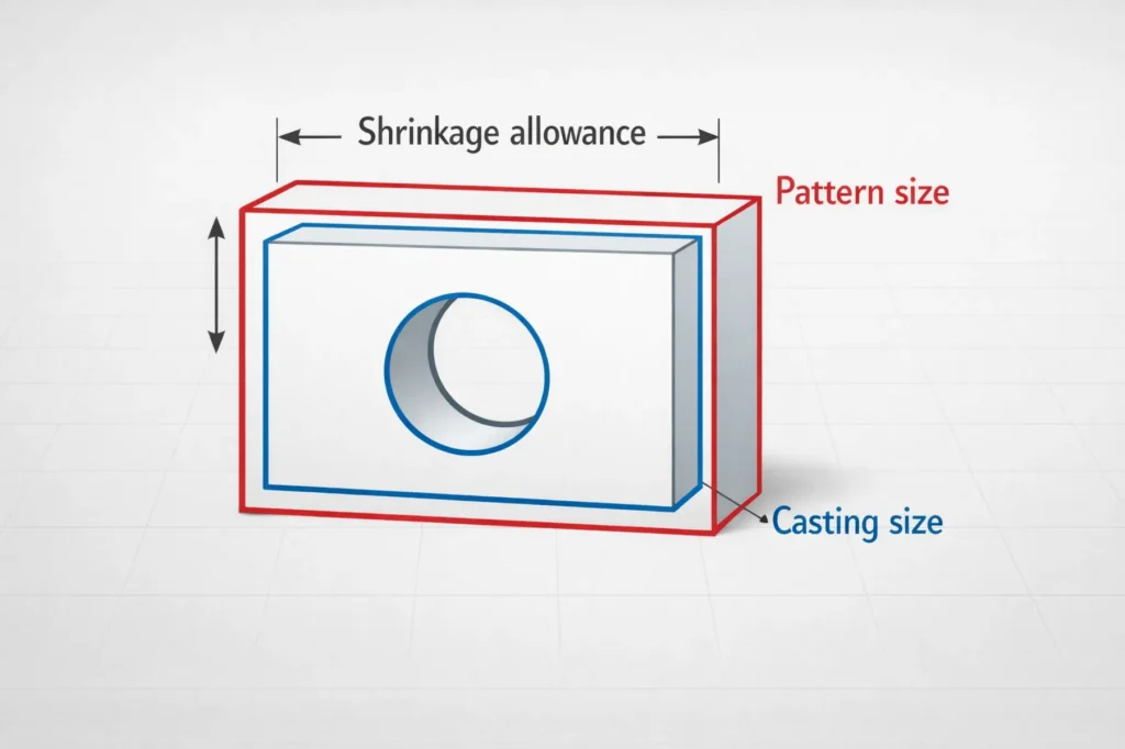
Shrinkage allowance in casting is the extra dimension added to a pattern in order to compensate for the size reduction that occurs as metal cools and solidifies. In simple terms, because a casting becomes smaller after cooling, the pattern must be made slightly larger so the final part can be closer to the required size.
Shrinkage allowance is a normal process compensation and should not be confused with machining allowance or shrinkage defects. Shrinkage allowance is used to compensate for dimensional change. Machining allowance is material intentionally left for later machining. Shrinkage defects such as cavities or porosity are more closely related to feeding and solidification control.
In actual production, shrinkage allowance is usually determined by material-based experience values, shrink rules, or historical process data. For simple castings with stable process conditions, an experience-based value may be a practical starting point. For larger, more complex, or tighter-tolerance parts, however, the final allowance often needs further adjustment based on trial runs and dimensional validation.
Types of Shrinkage in Castings
A casting does not shrink in only one single stage. During cooling and solidification, shrinkage usually appears in three main forms: liquid shrinkage, solidification shrinkage, and solid shrinkage. Understanding these stages helps explain why shrinkage allowance is needed and why certain castings may still develop shrinkage-related defects.
Liquid Shrinkage
Liquid shrinkage occurs when molten metal cools down before it begins to solidify. At this stage, the metal remains in liquid form, but its volume decreases as temperature drops. Although liquid shrinkage does not directly define the final part size by itself, it is still part of the overall shrinkage process.
Solidification Shrinkage
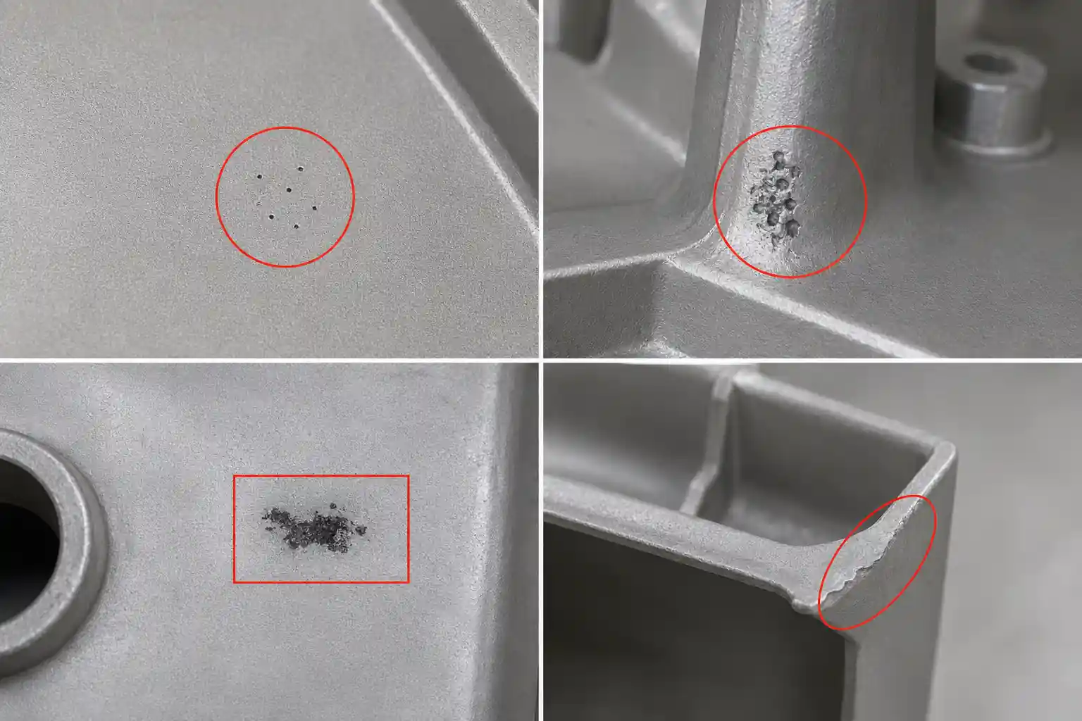
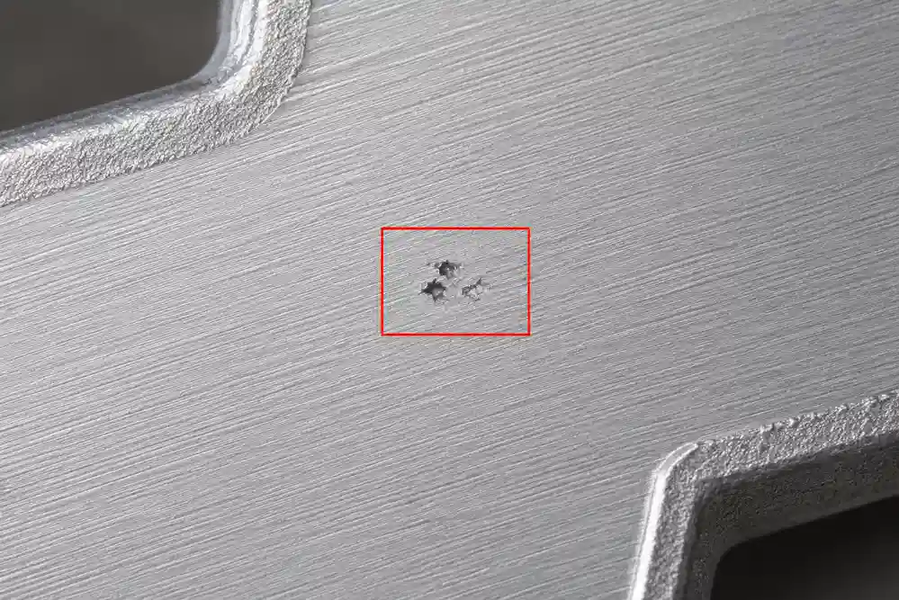
Solidification shrinkage occurs when metal changes from liquid to solid. This stage is especially important in casting because insufficient feeding during solidification can lead to shrinkage cavities, porosity, or other internal defects. For this reason, solidification shrinkage is closely related not only to dimensional compensation, but also to riser design, feeding paths, and hot spot control.
Solid Shrinkage
After the metal has fully solidified, it continues to contract as it cools to room temperature. This is called solid shrinkage. From the standpoint of pattern size compensation, solid shrinkage is one of the most directly relevant stages because the final dimensional reduction of the casting is largely reflected here.
Typical Shrinkage Rates for Common Materials
Different materials show different shrinkage behavior in casting, so shrinkage allowance cannot be treated as one fixed value for every project. In practice, foundries usually begin with material-based experience values and then adjust them according to process conditions, part geometry, and trial results.
| Material | Shrinkage Range |
|---|---|
| Gray cast iron | 0.55%–1.00% |
| Ductile iron | 1.00% |
| Cast steel / carbon steel | 2.00% |
| Aluminum | 1.65% |
| Aluminum alloys | 1.30%–1.60% |
| Brass | 1.30%–1.55% |
| Bronze | 1.05%–2.10% |
These values are better understood as reference starting points for pattern design rather than fixed answers that apply in every case. For castings with large wall-thickness variation, higher dimensional requirements, or more complex geometry, shrinkage allowance often needs further correction based on sample parts, first-article inspection, or past production data.
How Shrinkage Compensation Is Applied in Casting
Shrinkage compensation is usually based on the experience shrinkage rate of the selected material. In pattern design, the target casting dimension is enlarged in advance so that after cooling and shrinkage, the final casting can still approach the intended size.
A common way to understand it is:
Pattern size = Target casting size × (1 + shrinkage rate)
It can also be understood as first calculating the shrinkage compensation amount from the target size and material shrinkage rate, and then adding that value to the pattern dimension. For relatively simple castings with stable materials and process conditions, this approach can serve as a practical starting point.
However, shrinkage compensation is not a fixed percentage that can be mechanically applied to every casting. Alloy type, casting process, wall-thickness variation, ribs, bosses, core usage, and overall part geometry can all affect the actual shrinkage behavior. In general, the more complex the geometry, the less predictable the shrinkage becomes. That is why experience values often need to be adjusted through trial runs, first-article checks, or historical process data.
So when shrinkage allowance is applied in pattern design, the key is not just to assign a percentage. It is to begin with a material-based reference value and then refine it according to the actual geometry and process conditions.
How to Reduce Casting Shrinkage Problems
Two different issues need to be separated here. Shrinkage allowance is used to compensate for dimensional change in the pattern, while casting shrinkage problems are more closely related to inadequate feeding during solidification, hot spot distribution, and process control. In other words, a proper shrinkage allowance can help control final dimensions, but it cannot by itself eliminate shrinkage defects such as cavities or porosity.
Optimize Part Geometry
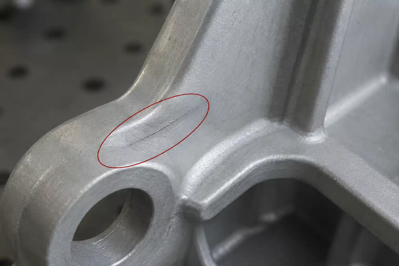
One of the most effective ways to reduce shrinkage problems is to avoid large wall-thickness variation and concentrated heavy sections. Uneven section transitions tend to create non-uniform solidification, which increases the risk of local shrinkage. Better wall distribution, smoother transitions, and reduced hot spot concentration can lower the difficulty of later process control.
Improve Feeding System Design
A properly designed gating and feeding system is essential for reducing shrinkage-related defects. More suitable riser placement, feeding paths, and hot spot management can reduce the likelihood of cavities and shrinkage porosity. In thicker sections or final solidification areas, feeding design is often more important than simply increasing pattern size.
Maintain Stable Process Conditions
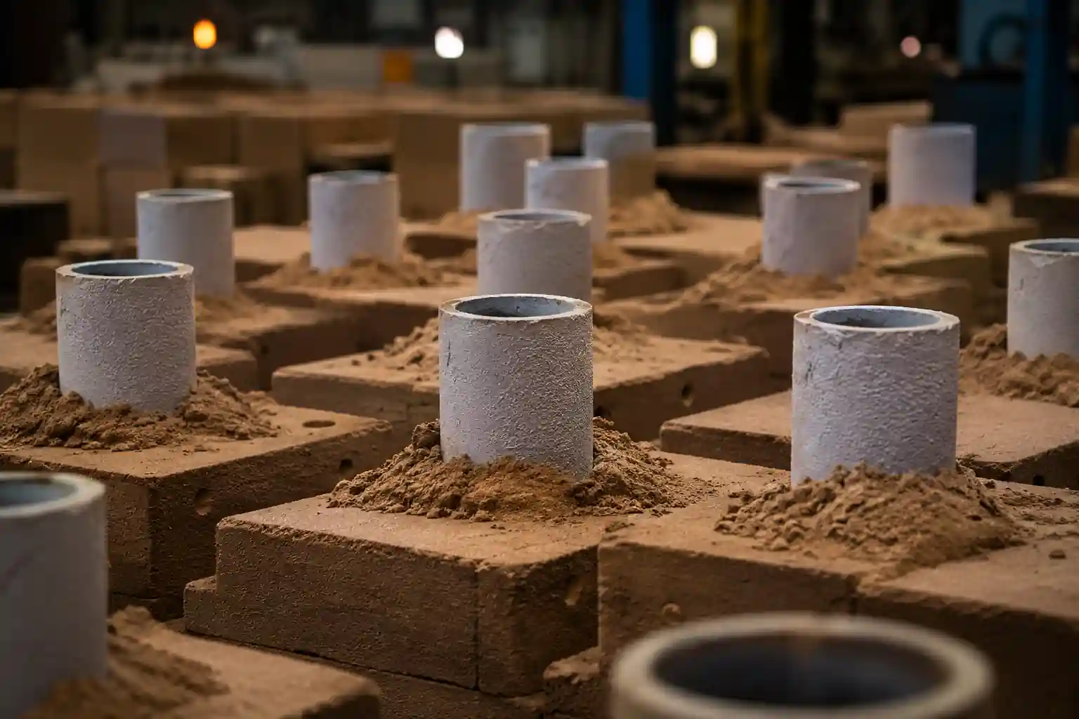
Pouring temperature, molding sand conditions, tooling system stability, and cooling conditions all affect actual shrinkage behavior. Even when the material is the same, unstable process conditions can lead to noticeable differences in dimensions and defect tendency. Stable process control is therefore an important foundation for reducing shrinkage problems.
Consider Machining Allowance and Tolerances Together
If the casting will be machined later, shrinkage allowance, machining allowance, and dimensional tolerance should be evaluated together. Only by considering all three within the same process logic can a foundry avoid undersized castings while still leaving sufficient stock for later machining.
Conclusion
Shrinkage allowance in casting is essentially the pattern size compensation used to account for the dimensional reduction that occurs as metal cools. It is one of the basic foundations of casting dimension control and directly affects pattern design, dimensional accuracy, and the practicality of later machining.
Because different materials show different shrinkage behavior, shrinkage allowance should not be treated as a single fixed value. It should be determined with reference to material type, process route, part geometry, and production experience. For foundry projects, the real goal is not simply to know a percentage, but to combine shrinkage compensation, dimension control, and shrinkage-problem prevention into a more stable manufacturing approach.