Choosing the right metal casting design is an important foundation for producing high-quality cast parts. Whether a design is suitable for casting will affect molten metal filling, solidification and feeding, mold release, cleaning, post-machining, and final inspection. For custom casting projects, engineers usually need to evaluate how different design factors affect casting quality and cost based on part size, structural complexity, material properties, tolerance requirements, and production volume. This article reviews the main considerations in metal casting design and helps identify potential issues that may affect production stability at the drawing stage.
Key Factors to Consider in Metal Casting Design
Balancing the functional requirements of a component with the physical realities of molten metal behavior is an engineering challenge. When evaluating a casting design, consider how the following parameters interact to define the production outcome.
Part Shape and Size
Part shape and size are usually the first considerations in metal casting design because they directly affect the choice of casting method. A small, complex part may be suitable for investment casting when better detail reproduction and surface quality are required, while a larger or heavier part is often more practical for sand casting because the process offers greater flexibility in casting size and weight.
The complexity of the shape also matters. Deep cavities, thin walls, internal holes, or irregular structures may require cores, special mold design, or additional machining after casting. For custom metal castings, a foundry will usually review the drawing first to determine whether the part shape and size match sand casting, investment casting, shell mold casting, or another suitable process. This makes shape and size one of the most important design factors before production begins.
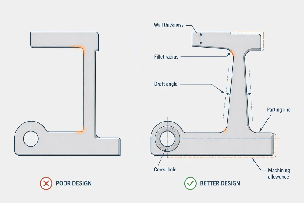
Wall Thickness
Consistency in wall thickness is perhaps the most significant factor in achieving a sound, defect-free casting. When metal cools, it shrinks; if an area is significantly thicker than the surrounding sections, it will remain molten longer and act as a thermal center, pulling metal from the thinner, already solidified sections. This leads to shrinkage porosity or internal voids.
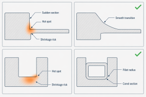
Avoid sudden transitions between thick and thin sections whenever possible. If a thick section is functionally necessary for strength, aim to taper the transition gradually. Remember that adding excess thickness does not always equate to a stronger part; in many cases, it creates a weaker, porous structure. Uniform wall thickness encourages a predictable solidification pattern.
Fillets and Radii
Sharp internal corners are stress concentrators. When molten metal solidifies, the shrinkage forces are directed toward these corners, often resulting in hot tears or cracks. Furthermore, sharp corners disrupt the smooth flow of molten metal, creating eddies and turbulence that can wash away sand grains or trap gas.
Incorporating generous fillets and radii into your design facilitates a smooth transition for both the metal flow and the solidification stresses. However, there is a balance to be struck; excessively large radii can inadvertently create localized thick sections. Aim for a radius that is sufficient to mitigate stress without introducing unnecessary bulk to the geometry.
Draft Angle
Draft angles are essential to ensure the pattern or the cast part can be removed from the mold without damaging the mold walls. A design without appropriate draft will inevitably lead to dragging, surface imperfections, or even mold collapse during the extraction process.
The amount of draft required is determined by the casting process, the height of the vertical surfaces, and the desired surface finish. Deeper or more complex pockets generally require larger draft angles. By incorporating these angles into the design from the start, you prevent the need for post-cast surface repairs or excessive machining to fix drag marks.
Parting Line
The parting line, where the two halves of the mold meet, is an unavoidable reality of the casting process. Its location influences everything from the flash (excess metal) removal to the final dimensional accuracy and surface appearance of the part.
During the design phase, evaluate where this line will fall. Ideally, it should be positioned where it least interferes with critical surfaces or complex functional geometries. A poorly placed parting line can make mold manufacturing significantly more difficult and complicate the subsequent cleaning and grinding operations.
Holes and Internal Cavities
Internal geometry is created using cores. While cores allow for incredible design flexibility—enabling the creation of cooling channels and weight-reduction structures—they also introduce complexity. Every core must be supported, vented, and secured within the mold to prevent it from shifting under the pressure of molten metal.
Complex core layouts increase the time required for cleaning, core sand removal, and final inspection. In some cases, it is more efficient to cast a solid shape and machine the internal hole or port post-casting, particularly for high-precision bores or threads that fall outside of typical casting tolerance ranges.
Shrinkage Allowance
Every metal alloy behaves differently as it transitions from a liquid to a solid state. As the metal cools, it contracts. Design engineers must account for this volumetric shrinkage, which varies based on the specific material grade being used.
Without considering shrinkage, the final part may be smaller than the required dimensions or suffer from internal voids. The casting process manages this through the design of feeding paths and risers—reservoirs of molten metal that replenish the shrinking part. Your design should allow for these pathways, ensuring that molten metal can reach the critical areas of your part as it cools.
Machining Allowance
Casting is rarely the final step for a precision component. Most parts require subsequent machining on specific surfaces, such as mounting faces, bearing seats, or sealing areas. The design must explicitly differentiate between “as-cast” surfaces and “machined” surfaces.
If insufficient machining allowance is provided, the tool may fail to “clean up” the surface. Conversely, providing excessive allowance adds unnecessary weight, increases material costs, and forces the tool to cut deeper, potentially exposing the more porous material closer to the center of the casting.
Tolerance Requirements
It is a common misconception to apply CNC machining tolerances to a cast part. Casting tolerances are dictated by the stability of the mold and the nature of the cooling metal; they are naturally broader than those achieved through subtractive manufacturing.
For critical dimensions, design the part with extra material (machining allowance) so that tight tolerances can be achieved through post-process machining. For standard structural features, use realistic casting tolerances. Demanding CNC-level precision on every dimension of a cast part will exponentially increase the cost of tooling, inspection, and rejection rates.
Material and Casting Process
The choice of material and casting process are closely connected. Common metal casting methods include sand casting, investment casting, shell mold casting, gravity casting, and die casting. Each process has different strengths in part size, wall thickness, surface finish, dimensional control, tooling cost, and production volume.
At MinHe, custom casting projects can be reviewed across several process routes, including sand casting, investment casting, shell mold casting, steel casting, cast iron casting, and aluminum casting. For example, sand casting is often more suitable for medium, large, or heavy castings, while investment casting may be considered for smaller parts with complex geometry and better surface requirements. Shell mold casting can be useful when the project needs better dimensional stability than conventional sand casting.
Process selection should not be based only on the material name or the final part shape. MinHe reviews the material grade, mechanical requirements, wall thickness, machining allowance, tolerance level, heat treatment, surface finish, inspection needs, and expected quantity together. This helps determine whether the part should follow a sand casting, investment casting, shell mold casting, steel casting, iron casting, or aluminum casting route before tooling begins.
How Design Factors Affect Casting Defects
Understanding the relationship between design choices and common defects is essential for any engineer working with cast parts.
| Design Factor | Possible Casting Problem | Design Direction |
| Sudden wall thickness changes | Shrinkage porosity, distortion | Keep section transitions balanced |
| Sharp internal corners | Stress concentration, cracking | Add suitable fillets and radii |
| Poor draft angle | Mold damage, surface drag marks | Review draft direction early |
| Complex internal cavities | Core shift, cleaning difficulty | Simplify core layout where possible |
| Insufficient machining allowance | Unfinished functional surfaces | Define machined surfaces clearly |
| Unrealistic tolerances | Higher cost, unstable production | Separate as-cast and machined tolerances |
Preparing a Casting Design for Review
When you are ready to engage a foundry for a DFM (Design for Manufacturing) review or to request a quote, having a well-prepared package saves time and ensures accuracy. A comprehensive design package should include:
- Material Grade: Or specific performance requirements.
- Overall Size and Weight: To help the foundry gauge material and furnace requirements.
- Critical Dimensions and Tolerances: Clearly marked to distinguish them from standard cast tolerances.
- Machined Surfaces: Highlighted to ensure correct machining allowance.
- Surface Finish Requirements: Especially for visible or sealing surfaces.
- Heat Treatment Requirements: If the part requires specific structural hardening.
- Inspection Requirements: Such as NDT or pressure testing.
- Estimated Production Quantity: This determines the tooling investment level.
- 3D Model: If available, to allow for advanced simulation and mold flow analysis.
Conclusion
Successful metal casting design is not only about making the part match the drawing. More importantly, it is about matching the part structure, material behavior, casting method, machining allowance, tolerance requirements, and production quantity. When these factors are reviewed early in the design stage, it becomes easier to reduce shrinkage defects, tooling changes, unfinished machined surfaces, dimensional variation, and unexpected costs.
For custom casting projects, MinHe can review drawings for steel castings, cast iron parts, aluminum castings, and sand casting projects. This helps identify potential risks in wall thickness, shrinkage, machining allowance, tolerances, surface requirements, and inspection needs. If the material or casting route has not been finalized, an early engineering review can help select a more practical casting solution before tooling or production begins.