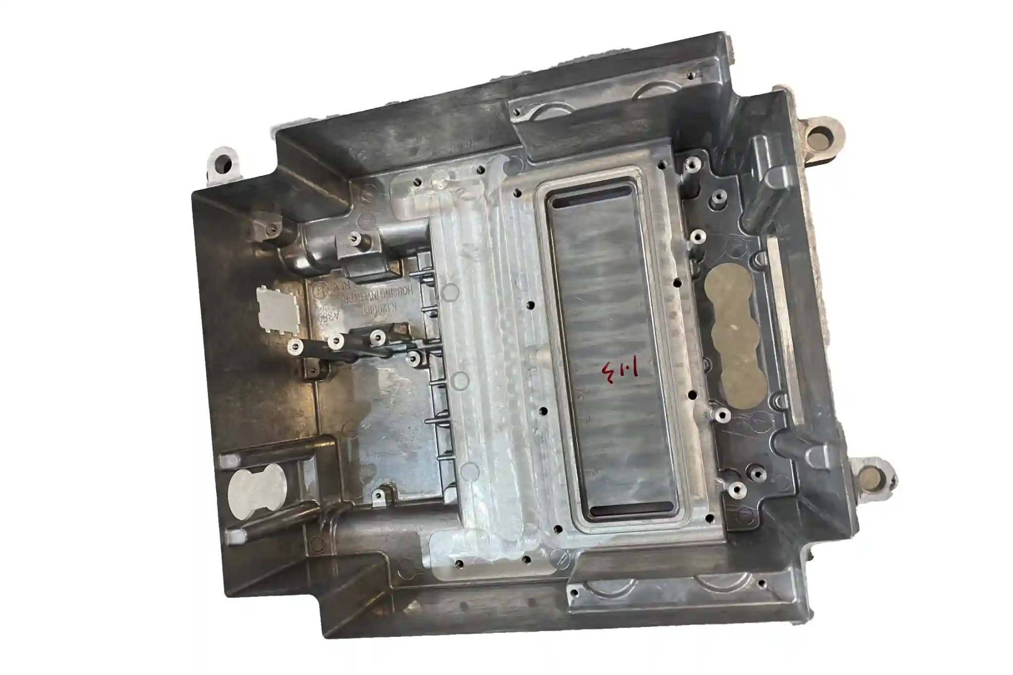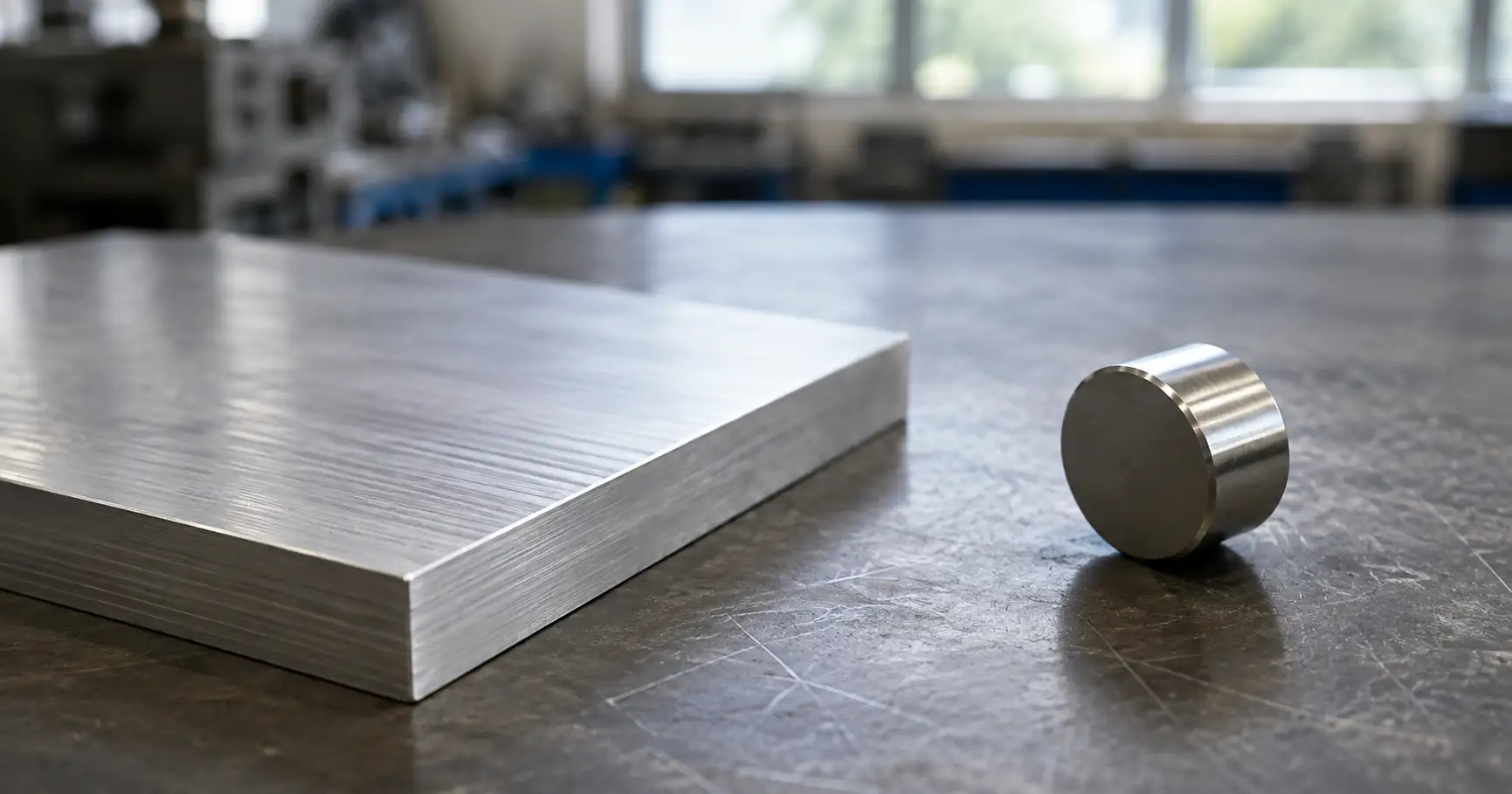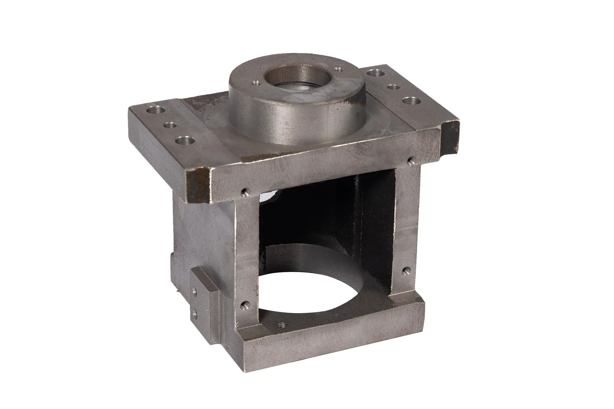



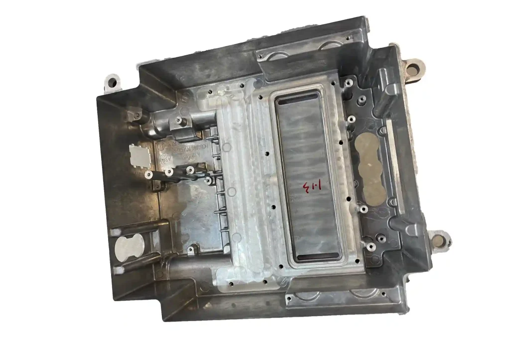
Aluminum motor housings protect internal components, provide structural support for mounting, and help dissipate heat. Depending on motor power, cooling method, structural loads, and production volume, they can be manufactured using high-pressure die casting, low-pressure casting, gravity casting, or sand casting. The selected alloy and casting process influence wall thickness, cooling-fin design, machining allowances, and inspection requirements.
This guide covers common aluminum alloys, manufacturing processes, structural design considerations, and quality inspection methods for motor housings. It also explains the key parameters to confirm when selecting a manufacturing solution and requesting a quotation.
Which Aluminum Alloy Is Right for a Motor Housing?
The casting process usually determines the practical range of alloy options. A356 or A357 is commonly considered for gravity, permanent-mold, or low-pressure casting when heat-treatment response, ductility, or internal soundness is a priority. For high-volume motor housings produced by high-pressure die casting, especially those with thin walls or closely spaced cooling fins, A380 and ADC12 are more common. These alloys offer good fluidity for filling complex geometries and support shorter production cycles.
How Motor Housings Are Cast
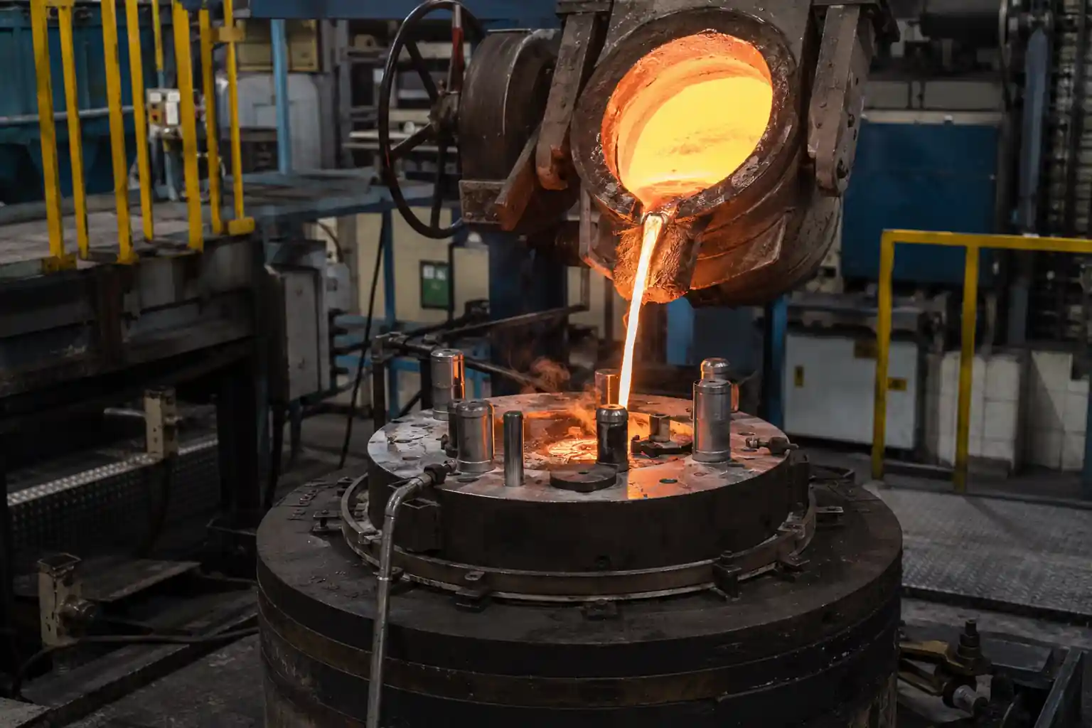
Aluminum motor housings can be produced by sand casting, gravity die casting, low-pressure casting, or high-pressure die casting. Process selection usually depends on production volume, housing size, wall thickness, and cooling-fin geometry, as well as requirements for leak tightness, heat treatment, and tooling budget. Each process can produce motor housings, but they suit different production stages and quality requirements.
Sand Casting
Sand casting is suitable for prototypes, large motor housings, and low-volume production. Tooling costs are relatively low, and design changes are easier to accommodate, making the process useful for prototype validation or projects with uncertain production demand.
Compared with permanent-mold casting and high-pressure die casting, sand castings generally have a rougher surface and lower dimensional consistency. Critical bores, mounting faces, and mating features therefore require larger machining allowances.
Gravity and Low-Pressure Casting
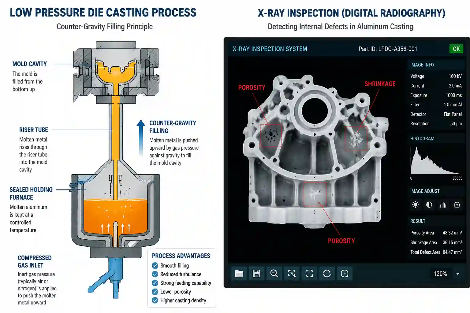
Gravity die casting and low-pressure casting are suitable for medium-volume production and motor housings that require better internal soundness, heat-treatment capability, or leak tightness. Their lower filling speeds create a more controlled metal flow, which can help reduce air entrapment and internal porosity.
These processes generally have longer cycle times and are less suitable than high-pressure die casting for very thin walls or closely spaced cooling fins. Bearing bores, stator bores, and sealing surfaces normally still require CNC machining.
High-Pressure Die Casting
High-pressure die casting is suitable for high-volume motor housings with complex geometries, thin walls, or closely spaced cooling fins. Molten aluminum fills the die at high speed and pressure, allowing the process to form fine features while providing good dimensional repeatability and production efficiency.
The process requires a higher initial tooling investment, but the tooling cost can be distributed across a larger number of parts as production volume increases. Conventional high-pressure die casting also requires careful control of air entrapment and internal porosity, particularly around thick sections, sealing surfaces, and areas that will be machined. For housings with demanding leak-tightness requirements, vacuum die casting, squeeze casting, or other processes designed to improve internal casting quality may be considered.
Design Rules for Motor Housing Castings
A typical motor housing combines a cylindrical body with mounting feet, end flanges, cooling fins, and terminal-box bosses. Changes in section thickness around these features affect metal flow and cooling rates, which can lead to incomplete filling, shrinkage porosity, or dimensional distortion. Good casting design therefore requires each feature to meet its functional purpose without creating unnecessary mass or abrupt wall transitions.
| Design Feature | Recommended Practice | Potential Manufacturing Risk |
|---|---|---|
| Housing walls | Maintain a consistent wall thickness and use gradual transitions between thick and thin sections | Incomplete filling, hot spots, shrinkage, and distortion |
| Ribs | Use ribs to improve stiffness instead of increasing the overall wall thickness; avoid heavy rib intersections | Shrinkage at rib roots, local stress, and uneven cooling |
| Cooling fins | Coordinate fin thickness, spacing, height, and orientation with metal flow and die-opening direction | Misruns, incomplete filling, sticking, and ejection damage |
| Bosses and mounting feet | Blend these features into the housing wall with suitable fillets or supporting ribs | Localized metal accumulation, hot spots, and shrinkage porosity |
| Fillets and radii | Replace sharp corners with smooth transitions while avoiding excessive local thickness | Stress concentration, restricted metal flow, and die thermal fatigue |
| Draft angles | Provide sufficient draft on surfaces parallel to the die-pull direction | Drag marks, sticking, ejection distortion, and increased die wear |
| Machined features | Leave appropriate machining stock on bearing bores, end faces, sealing surfaces, and datum features | Incomplete cleanup, excessive machining, and exposure of subsurface porosity |
Before tooling is released, the proposed parting line, gate, vent, and ejector-pin locations should be reviewed to ensure they do not interfere with sealing surfaces, bearing bores, machining datums, or cosmetic areas. Where the geometry presents a higher risk, filling and solidification simulations can help identify possible air entrapment, hot spots, shrinkage, and distortion before the die is manufactured.
Thermal Management and Cooling Design for Motor Housings
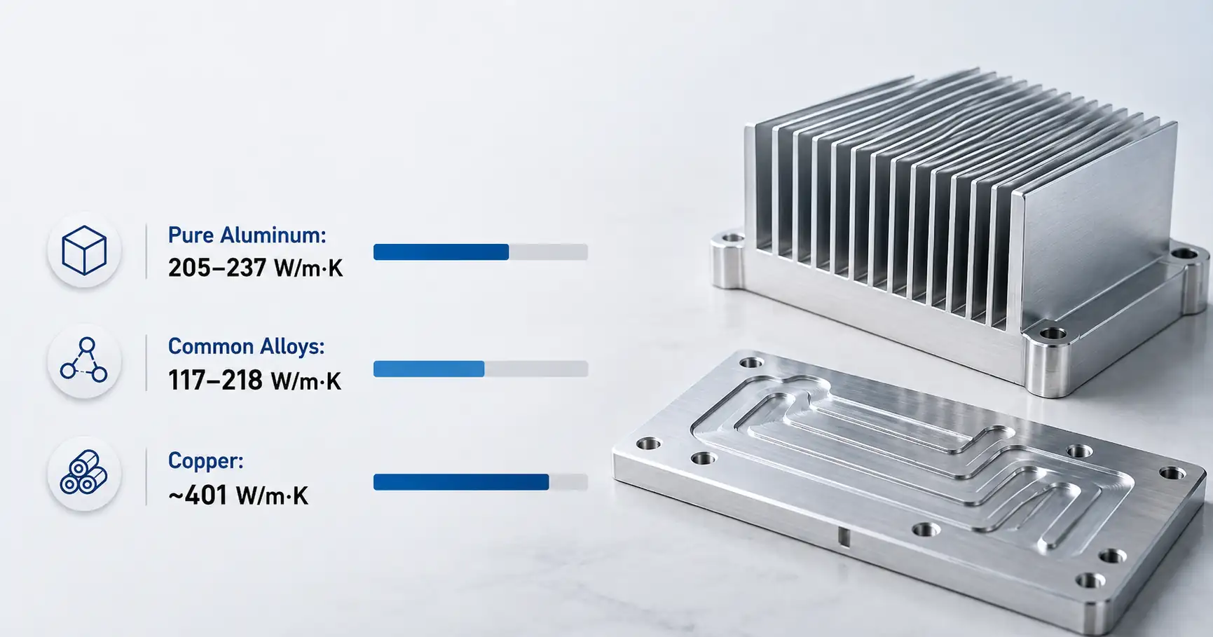
Heat generated during motor operation typically passes through the contact area between the stator and housing, travels through the housing wall, and is then dissipated by cooling fins, airflow, or liquid coolant. The thermal performance of a motor housing depends not only on the conductivity of the aluminum alloy but also on the contact area, wall thickness, cooling-fin geometry, and surface treatment.
For air-cooled motor housings, the fins should be oriented to work with the primary airflow and connected continuously to the housing wall. Fins that are too thin or closely spaced may be difficult to fill and eject, while overly thick fin roots can cause uneven cooling. Fin thickness, spacing, and height must therefore balance heat-dissipation requirements with casting feasibility.
Liquid-cooled motor housings require cooling passages to be positioned close to the stator mounting area and other major heat sources. The design must also provide sufficient wall thickness around the passages and sealing interfaces. Thin passage walls may increase leakage risk, while excessive local thickness around ports and transitions can create hot spots and shrinkage porosity.
Coatings and machined surfaces can also affect heat transfer. Thermal contact areas should have controlled surface conditions and be masked from coating where necessary. If the housing also provides an electrical grounding path, the required grounding surfaces and coating exclusions should be clearly identified on the drawing.
Machining and Dimensional Control for Motor Housings
After casting, the stator bore, bearing bores, end-cover pilots, sealing surfaces, and mounting faces usually require CNC machining. These features establish the positional relationships between the motor components. The drawing should therefore distinguish as-cast surfaces from machined surfaces and define a datum system based on the functional assembly requirements.
Machining stock must be sufficient to clean up normal casting variation without leaving excessive material. Insufficient stock can prevent a bore or face from being fully machined. Excessive stock increases machining time and may expose subsurface porosity. Fixtures should support the housing at rigid locations without forcing the cylindrical body into a temporarily round condition that changes after unclamping.
| Critical Feature | Main Control Requirements | Potential Problems |
|---|---|---|
| Stator bore | Diameter, roundness, cylindricity, and fit | Difficult assembly, loss of retention, or inconsistent thermal contact |
| Bearing bores and end-cover pilots | Size, coaxial relationship, and runout | Vibration, noise, misalignment, or abnormal bearing wear |
| Mounting faces | Flatness and orientation relative to the motor axis | Installation error or poor assembly alignment |
| Sealing surfaces | Flatness, surface finish, and complete machining cleanup | Seal failure or coolant leakage |
| Machining stock | Casting variation, cutting depth, and stock distribution | Incomplete cleanup, longer machining time, or exposed porosity |
| Fixturing points | Support locations, clamping force, and free-state deformation | Changes in roundness or feature position after unclamping |
After machining the first production samples, a coordinate measuring machine can be used to inspect the critical bores and mounting surfaces according to the datum sequence specified on the drawing. For thin-walled or asymmetric housings, dimensions should also be compared while the part is clamped and after it is released to determine whether fixturing causes measurable distortion.
Quality Inspection and Validation
Inspection requirements should match the function of each motor housing feature. Critical bores, end-cover pilots, mounting faces, and sealing surfaces can be checked by CMM using the datum system specified on the drawing. Liquid-cooled or sealed housings may also require pressure or leak testing.
During process development, X-ray inspection or sectioning can be used where internal porosity presents a significant risk. First-article results should confirm that the selected casting, machining, and inspection methods can consistently meet the drawing requirements. PPAP documentation can be provided when required for automotive programs.
MinHe Foundry Motor Housing Capabilities
| Capability | Available Support |
|---|---|
| Casting processes | Sand casting, gravity die casting, and low-pressure casting |
| DFM review | Wall thickness, draft angles, parting requirements, machining stock, and datum planning |
| CNC machining | Stator bores, bearing bores, mounting faces, sealing surfaces, and other critical features |
| Dimensional inspection | CMM inspection of machined features and drawing tolerances |
| Quality planning | Inspection requirements based on the housing application and drawing |
| Project review | Evaluation of drawings, operating conditions, production volume, and validation requirements |
Request a Motor Housing Casting Review
Send your 2D or 3D drawings, operating conditions, and target production volume to the MinHe Foundry engineering team. We will review the proposed casting process, wall sections, machining allowances, datum scheme, and inspection requirements before tooling begins.