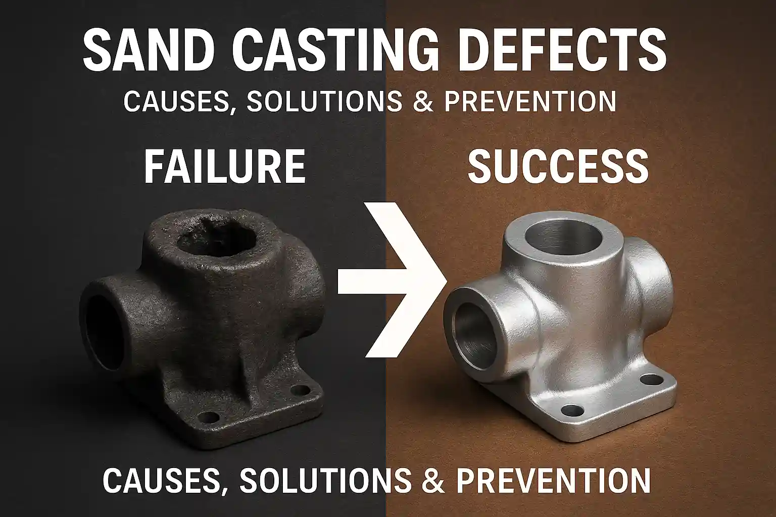
Understanding Casting Defects in Foundry Practice
Casting defects are flaws or irregularities that occur during the casting process, potentially compromising the structural integrity, dimensional accuracy, or appearance of the final product. In industries relying on high-performance components—such as automotive, construction, or hydraulics—understanding how and why these defects arise is critical for both producers and buyers.
This guide outlines the most frequent casting defects encountered in ductile iron, grey iron, and steel castings. For each, we cover typical visual indicators, underlying causes, preventive strategies, and possible remedies.
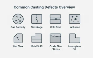
Visual overview of eight common casting defect types illustrated with icons and labels.
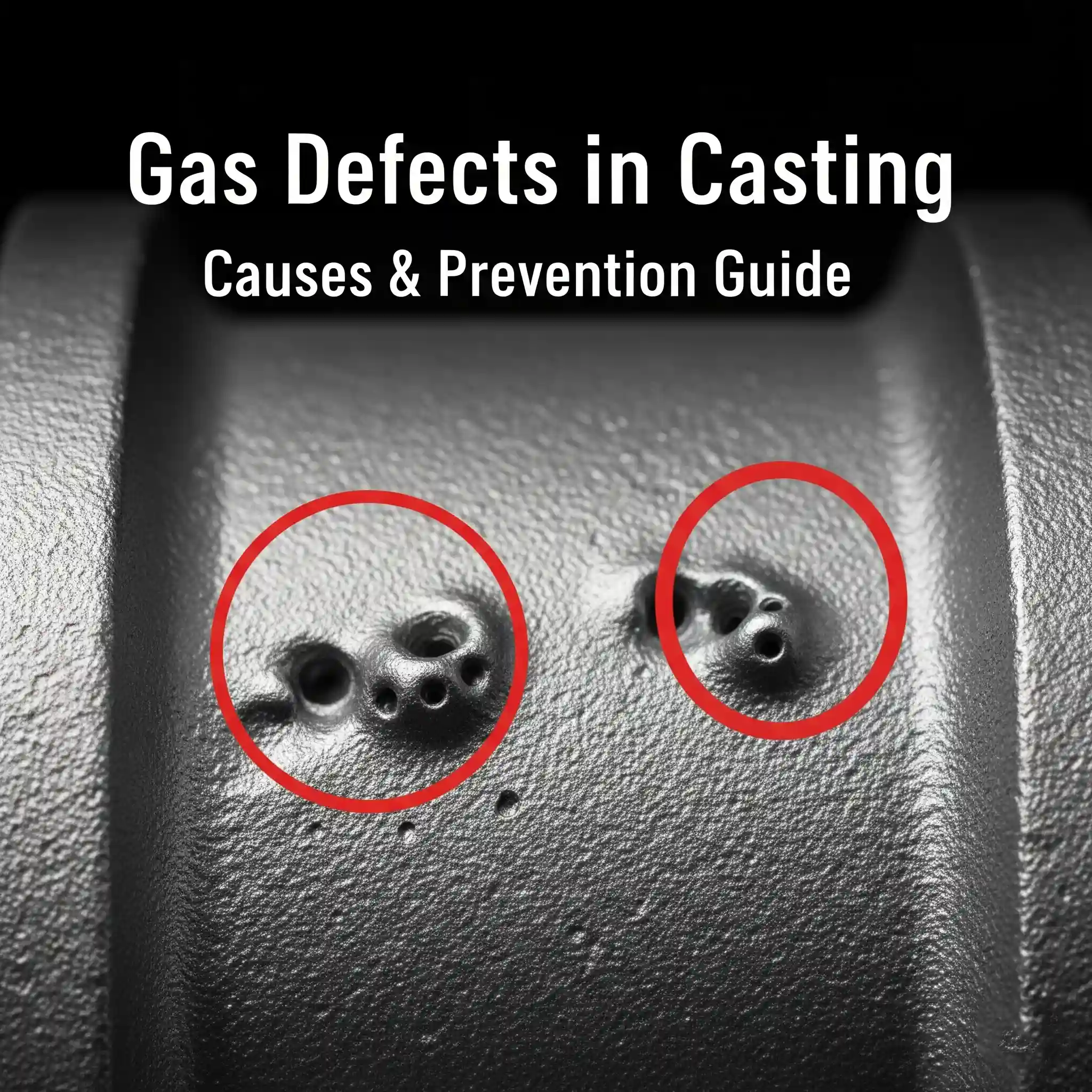
Gas Porosity
Typical appearance: Small, rounded cavities or voids either on the surface or embedded within the casting. These are especially problematic in pressure-retaining components like pump housings or valve bodies.
👉 Note: Industry studies indicate that gas porosity and shrinkage together account for up to 50% of all casting defects, making them the most common and critical types to monitor.
Causes:
Gas porosity in ductile iron and steel castings typically results from gas entrapment during solidification. This can be caused by:
- Excessive moisture in mold or core materials
- Incomplete degassing of molten metal
- Poor mold venting or excessive turbulence during pouring
- Use of high-resin content binders that decompose into gas
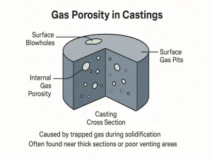
Typical appearance of gas porosity and surface blowholes in metal castings due to trapped air or moisture.
Prevention:
- Ensure molds and cores are thoroughly dried
- Use low-hydrogen, high-purity charge materials
- Optimize gating design to minimize turbulence
- Employ argon or nitrogen degassing during melt treatment
Solutions:
- Minor porosity may be addressed through weld repair or impregnation
- For persistent issues, simulation software can help visualize gas flow and improve mold design
Shrinkage Cavities
Typical appearance: Internal voids or sunken areas typically located in thicker sections or areas far from effective riser feeding. These often occur in large ductile iron housings, bearing blocks, or steel base plates.
👉 Note: Shrinkage cavities are particularly problematic in structural castings, as they can lead to stress concentration points that significantly reduce mechanical strength and fatigue life.
Causes:
Shrinkage cavities form during the final stage of solidification, when molten metal fails to feed regions that are still contracting. Contributing factors include:
- Undersized or poorly positioned risers
- Lack of directional solidification control
- Premature freezing of feeder necks
- Thick cross-sections with uneven cooling rates
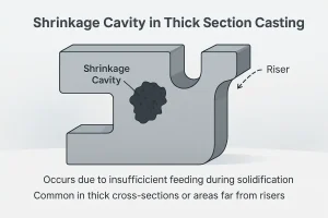
A typical shrinkage cavity caused by solidification in thick sections
Prevention:
- Proper riser design with modulus matching to critical zones
- Use of chills to guide heat dissipation
- Insulating sleeves to slow down riser solidification
- Adjust casting orientation to promote top-down solidification
Solutions:
- Modify casting geometry or increase feeder volume
- Repair cavities using arc welding or metal spray (where allowed by spec)
Cold Shut (Misrun)
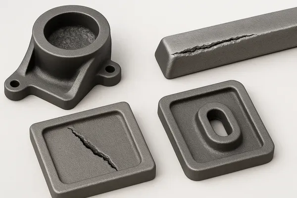
Typical appearance: Thin, linear discontinuities or unfused seams at junctions where two metal fronts failed to merge. Often seen in thin-walled castings, complex geometries, or at horizontal joints.
👉 Note: While cold shuts are usually visible on the surface, they may also form internal cracks in critical zones, potentially compromising sealing surfaces or causing premature failure under pressure.
Causes:
Cold shuts occur when partially solidified metal flows meet but fail to fuse due to:
- Low pouring temperatures
- Poor fluidity of the alloy
- Long flow paths or sharp corners in mold design
- High heat loss through cores or metal chills
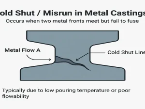
Cold shut defect occurs when two molten metal fronts fail to fuse properly, leaving a visible line or seam.
Prevention:
- Increase pouring temperature within alloy-specific limits
- Shorten flow length by relocating gates closer to critical areas
- Use rounded transitions and fillets in pattern design
- Avoid undersized ingates that restrict flow rate
Solutions:
- Modify gating system to reduce velocity loss
- Improve alloy selection or use flow-enhancing inoculants
- If structural integrity is not compromised, localized repair may be possible
Inclusions (Slag / Sand / Oxides)
Typical appearance: Dark or brittle particles embedded in the casting, visible on machined surfaces or through NDT inspection. These may originate from slag, eroded sand, or oxide films.
👉 Note: Inclusions are among the most difficult defects to detect early, as they often remain hidden until machining or in-service failure occurs—especially in high-pressure or fatigue-sensitive applications.
Causes:
Non-metallic inclusions arise from various contamination sources:
- Incomplete slag removal during melt handling
- Sand erosion from the mold cavity during filling
- Reoxidation caused by metal turbulence
- Loose core sections or insufficient coating on mold walls
Prevention:
- Use slag conditioners and perform thorough ladle skimming
- Introduce ceramic foam filters at ingates
- Maintain consistent mold strength and surface finish
- Reduce pouring height to minimize splash and turbulence
Solutions:
- Surface inclusions may be removed by machining
- Deep inclusions require rejection or recasting, especially in critical structural parts
- Metallurgical audits can trace inclusion types back to specific process steps
Hot Tears / Thermal Cracks
Typical appearance: Jagged or branched cracks, usually occurring at sharp corners, bosses, or junctions of varying wall thickness. These defects form during the final stages of solidification when the casting cannot accommodate internal thermal stresses.
Causes:
Hot tears are often the result of mechanical restraint or poor mold collapsibility. Key contributing factors include:
- Abrupt changes in wall thickness
- Rigid sand molds with low collapsibility
- High pouring temperatures causing wide solidification intervals
- Inadequate fillets or stress-relief features in design
Prevention:
- Uniform wall thickness and smooth geometric transitions
- Improved mold materials or additives that enhance collapsibility
- Control of pouring temperature and mold preheat
- Inclusion of relief notches and flexible cores
Solutions:
- Minor cracks may be repaired with welding (if specifications allow)
- Long-term correction typically involves geometric redesign or alternative molding materials
Mold Shift / Core Displacement
Typical appearance: Stepped surfaces or dimensional misalignment between different halves of the casting, resulting in inconsistent wall thicknesses or offset holes.
Causes:
Mold shift is caused by misalignment between the cope and drag, or movement of internal cores. This can occur due to:
- Inadequate clamping force or loose flask fit
- Pattern wear or damaged dowel pins
- High metallostatic pressure or jarring during pouring
Prevention:
- Strengthen flask fixtures and ensure accurate mold registration
- Replace worn pattern equipment and core prints
- Adjust pouring height to reduce metal pressure
Solutions:
- Machining may be possible if tolerances permit
- Rebuild or upgrade pattern tooling and alignment systems
Oxide Films / Dross Defects
Typical appearance: Thin, film-like layers or brittle flakes near the casting surface, often only discovered during machining or under metallographic analysis. These inclusions weaken fatigue resistance.
Causes:
Oxide-related defects form due to:
- Exposure of molten metal to oxygen during pouring
- Excessive turbulence in the gating system
- Reoxidation caused by improper ladle handling or delay
Prevention:
- Use a protective atmosphere (argon) or flux to reduce oxidation
- Optimize gating geometry to enable laminar flow
- Minimize metal turbulence by controlled pouring speed
Solutions:
- Surface oxide can sometimes be removed by machining
- Deep internal oxides require recasting and gating revision
- Thermal analysis tools can help optimize melt practice
Incomplete Fill (Underfilling)
Typical appearance: Missing sections, incomplete corners, or short fills in castings—especially in thin-walled or large surface-area parts.
Causes:
This defect is caused by molten metal failing to completely fill the mold cavity before solidifying. Common reasons include:
- Low pouring temperature or poor fluidity
- Gating design that restricts flow or induces early turbulence
- Gas backpressure due to poor venting
- Overly complex mold features
Prevention:
- Increase pouring temperature within alloy limits
- Improve gating ratio and mold cavity air escape
- Simplify casting geometry or divide into multi-part designs
- Apply vacuum-assist techniques where applicable
Solutions:
- Evaluate fill simulations to locate problematic zones
- Recast with corrected flow and venting systems
Non-Destructive Testing Methods for Casting Defects
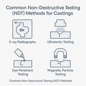
Common NDT methods used for casting inspection: X-ray, Ultrasonic, Dye Penetrant, and Magnetic Particle Testing.
| Testing Method | Detectable Defects | Suitable Materials / Uses | Notes |
|---|---|---|---|
| X-ray Radiography | Internal shrinkage, porosity, voids | Complex castings, thick-wall parts | Excellent detail; more expensive |
| Ultrasonic Testing | Subsurface cracks, inclusions | Large sections, steel/ductile iron | Requires operator skill and good surface |
| Dye Penetrant Testing | Surface cracks, cold shuts | Non-porous metals (aluminum, steel) | Simple, affordable; only surface-visible |
| Magnetic Particle | Surface and near-surface flaws | Ferrous metals (cast iron, steel) | Fast and reliable; limited to magnetic parts |
These testing methods help identify internal or external defects before machining or delivery, ensuring your cast components meet dimensional and performance specifications.
Final Thoughts
Casting defects can significantly affect performance, cost, and customer satisfaction. With a clear understanding of each defect’s causes and corrective strategies, foundries and buyers alike can take a proactive role in quality assurance.
Looking for technical support or defect analysis? Contact our team for expert guidance and custom casting solutions.