Lost Foam Casting (LFC), also widely referred to as Evaporative Pattern Casting (EPC), represents a distinctive class of near-net-shape foundry processes. Unlike traditional methods where the pattern is withdrawn from the mold, LFC utilizes an expanded polystyrene (EPS) or polymer pattern that is evaporated upon contact with molten metal, leaving behind a cavity perfectly shaped for the final component.
This method, recognized for its efficiency in consolidating multiple components and achieving complex internal passageways, provides a strategic manufacturing route for materials like ductile iron, gray iron, and aluminum alloys. For engineers, manufacturing project managers, and procurement personnel, understanding the technical mechanism and comparative performance of LFC is crucial for informed process selection. This article provides a comprehensive evaluation of the LFC process, materials, advantages, limitations, and its standing against competing foundry technologies like Investment and Green Sand casting.
What Is Lost Foam Casting (EPC)
Lost Foam Casting (LFC), or Evaporative Pattern Casting (EPC), is a molten metal processing technique that employs a pattern made of a material that vaporizes when heated, typically Expanded Polystyrene (EPS) or Polymethyl Methacrylate (PMMA). The core principle involves replacing this evaporative model directly with liquid metal without a prior pattern withdrawal step.
The primary purpose of LFC is to eliminate the need for cores, core prints, and parting lines, thus simplifying the mold structure and allowing for the economic production of highly intricate parts with single-piece construction. The pattern is encased in unbonded, dry sand, which is supported by a vacuum, ensuring the structural integrity of the mold during the pour. When the molten metal is poured into the system, the high temperature instantly vaporizes the foam, creating a transient cavity that the metal fills. The gaseous decomposition products are vented through the refractory coating and the surrounding sand, making near-net-shape parts possible with excellent dimensional stability.
How the Process Works
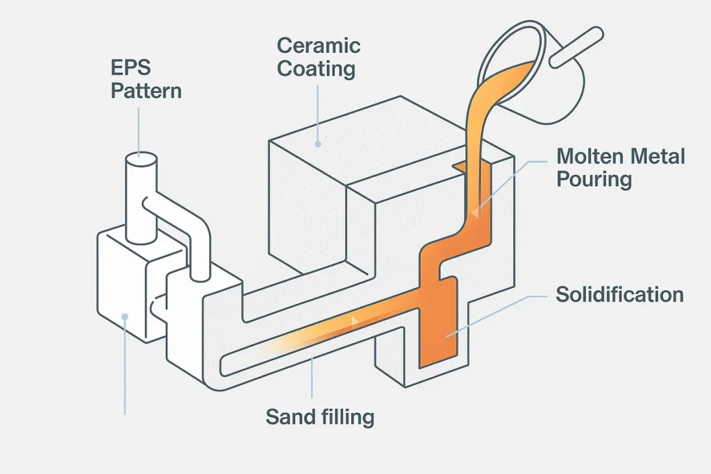
The complete Lost Foam casting process is a specialized sequence designed to manage the thermal decomposition of the polymer pattern while maintaining mold stability via vacuum and dry sand support.
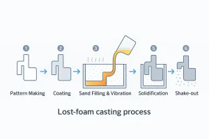
Step-by-step diagram of the lost foam casting process, illustrating each phase from foam pattern preparation to shake-out after solidification.
Pattern Production and Preparation
The process begins with the production of the foam pattern. EPS or PMMA beads are expanded and molded into the precise shape of the final part. These patterns are highly fragile and require careful handling. For larger or more complex assemblies, individual foam segments are joined together using hot melt glue or other adhesives—a process known as clustering or assembly. This allows for multiple castings to be produced from a single pour, increasing efficiency.
Coating Application
Once the pattern is complete and assembled into a cluster, it is coated with a thin, water-based refractory slurry. This coating serves three critical functions: (1) providing the necessary mold wall to withstand the force of the molten metal, (2) providing sufficient permeability to allow the gaseous byproducts of the foam to escape, and (3) offering a smooth surface for the final casting. The coating thickness must be precisely controlled for optimal performance.
Sand Filling and Vacuum Stabilization
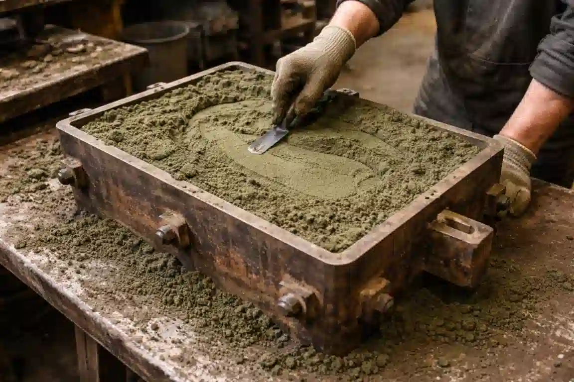
The coated foam cluster is then placed in a flask, which is filled with unbonded, dry silica sand. The sand is compacted around the pattern using vibration tables (a process called dry sand densification) to ensure maximum contact and support for the fragile foam structure. A critical step follows: the flask is sealed, and a vacuum is applied. This vacuum is maintained throughout the casting sequence; it stabilizes the dry sand, preventing collapse, and assists in drawing the gaseous foam decomposition products away from the metal front.
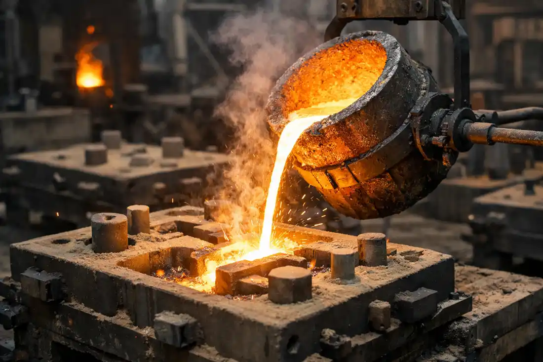
Pouring and Evaporation
The molten metal is poured into the sprue (vertical channel) of the stabilized flask. As the metal front advances, the intense heat instantly vaporizes the foam pattern—a process often referred to as pyrolysis or thermal decomposition. The metal effectively replaces the foam volume, creating the casting. The resulting gas must escape rapidly through the permeable refractory coating and the vacuum-assisted dry sand.
Solidification and Cleanup
Once the metal has solidified, the vacuum is released. The unbonded dry sand flows freely away from the solidified casting, simplifying the cleaning process. Because the sand is dry and unbonded, it is highly recyclable, and the minimal amount of refractory coating left on the casting surface requires less aggressive post-processing compared to traditional sand molds.
Patterns & Materials
The material selection for the pattern and the molding environment are fundamental to the success and precision of LFC.
The evaporative material is typically Expanded Polystyrene (EPS) for less complex patterns and higher volume runs, or Polymethyl Methacrylate (PMMA) for patterns requiring higher detail and better surface finish due to its cleaner decomposition. The foam patterns are typically manufactured using expansion molding or, for low volumes or prototypes, machined directly from solid foam blocks.
The refractory coating (or wash) is a critical interface, composed of a refractory material (like aluminum silicate, zircon, or magnesia) suspended in a water-based binder. The properties of the coating—specifically its thickness, thermal conductivity, and permeability—must be precisely tuned to manage the massive influx of gas generated upon metal contact.
The dry sand used is typically unbonded silica sand, providing a stable, free-flowing medium that can be easily densified by vibration. The maintenance of the required vacuum range (typically 250–500 mm Hg) is essential to ensure sand consolidation and efficient gas removal.
LFC is highly suitable for casting a variety of common alloys, particularly those that benefit from the process’s high dimensional accuracy:
- Ferrous Alloys: Gray iron, ductile iron, and certain steel grades (favored in the automotive sector).
- Aluminum Alloys: Used extensively for engine blocks, cylinder heads, and brackets where lightweight and geometric complexity are key requirements.
- Copper Alloys: Less common, but used where complex, near-net-shape brass or bronze parts are needed.
Advantages & Limitations
LFC is selected over competing methods when the component’s geometry and complexity outweigh the production cycle time constraints.
Key advantages of Lost Foam Casting include:
- Elimination of Parting Lines and Cores: Since the pattern is not withdrawn, no draft angles or mold splitting is required. This eliminates defects associated with parting lines and core placement, resulting in a single-piece component with improved structural integrity.
- Superior Complexity and Design Freedom: The ability to pre-assemble foam segments allows for the creation of intricate internal cavities and complex shapes that would be impossible or prohibitively expensive with Green Sand casting (due to core dependency).
- Near-Net-Shape (NNS) Manufacturing: LFC achieves excellent dimensional accuracy and surface finish (typically Ra 6.3–12.5 µm), significantly reducing the need for post-casting machining and lowering overall production costs.
- Reduced Material Handling: The use of unbonded sand and the high pattern-to-casting ratio in clusters simplifies mold preparation and casting removal.
However, the limitations of LFC must be managed carefully:
- Gas Management and Defects: The thermal decomposition of the foam generates a large volume of gaseous products. Poor coating permeability or inadequate vacuum can lead to critical defects like porosity, incomplete filling, or carbon residue inclusions on the casting surface.
- Pattern Cost and Storage: The foam patterns, particularly those made from PMMA, can be expensive to produce. They are also bulky and highly susceptible to damage during storage and handling, impacting logistic costs.
- Batch Size and Cycle Time: The process is inherently limited by the time required for coating application, drying, and cluster assembly. It is not suitable for ultra-high-volume, high-speed production (like die casting) or extremely small, rapid prototyping runs.
- Surface/Dimensional Variation: While good, surface quality and dimensional consistency can be slightly inferior to Investment Casting due to variations in foam density and coating thickness.
Lost Foam vs Investment Casting
Both LFC and Investment Casting (Lost Wax) utilize an evaporative pattern, making them competing processes for near-net-shape precision.
| Feature | Lost Foam Casting (LFC) | Investment Casting (IC) | Strategic Difference |
|---|---|---|---|
| Pattern Material | EPS/PMMA (Low Density) | Wax (High Density) | Wax patterns offer higher detail but are fragile. |
| Mold Material | Refractory Coating in Dry Sand | Ceramic Shell (Refractory Slurry) | IC mold is self-supporting; LFC requires vacuum/sand. |
| Surface Finish (Ra) | Good (Ra 6.3–12.5 µm) | Superior (Ra 0.8–3.2 µm) | IC wins on surface finish and detail. |
| Dimensional Tolerance | High (±0.3–0.5 mm/100 mm) | Very High (±0.1–0.25 mm/100 mm) | IC is generally more precise. |
| Cost Driver | Pattern Tooling (medium) & Volume | Wax Die Cost (very high) & Wax Material | LFC is cheaper for large, complex parts in medium batches. |
| Size & Weight | Excellent for large/heavy parts (e.g., engine blocks) | Limited to small/medium parts | LFC is scale-independent; IC is size-limited. |
| Alloy Suitability | Fe, Al, Cu alloys (Lower Temp) | Nearly all alloys (including superalloys) | IC allows for higher melting point materials. |
LFC is the preferred choice when casting large, complex iron or aluminum parts where the cost of a large wax die for IC would be prohibitive. IC is chosen when ultimate precision and surface finish, particularly for high-temperature alloys, are non-negotiable.
Lost Foam vs Green Sand
The comparison between LFC and traditional Green Sand casting revolves around complexity, dimensional precision, and mold structural requirements.
| Feature | Lost Foam Casting (LFC) | Green Sand Casting | Strategic Difference |
|---|---|---|---|
| Mold Type | Evaporative pattern, unbonded sand | Reusable pattern, bonded sand (clay/chemical) | LFC simplifies mold removal and sand processing. |
| Cores & Parting Lines | None needed | Requires cores, core prints, and parting lines | LFC handles internal complexity far better. |
| Draft Angle | None required | Required for pattern withdrawal (typically 1–3°) | LFC offers greater design freedom. |
| Component Consolidation | High (Multi-part assemblies) | Low (Limited by core complexity) | LFC excels at “one-piece” manufacturing. |
| Cycle Time & Cost | Medium speed, low cleanup cost | High speed, lower tooling cost | Green Sand is faster for simple, high-volume parts. |
| Applicable Parts | Complex internal passages, pump housings | Simple external shapes, high volume, low detail | Sand is best for basic geometry. |
Green Sand is the go-to method for very high-volume production of simple parts requiring minimal detail. LFC is the superior choice for parts that need internal complexity or consolidation into a single casting, where the expense and labor of core assembly in Green Sand casting would eliminate cost savings.
Applications & Industry Use
Lost Foam casting is a highly specialized process whose benefits are most pronounced when manufacturing parts that traditionally required extensive core work or complex internal features.
The process is heavily utilized in:
- Automotive Structural Components: LFC is the benchmark for casting intricate aluminum components, including engine blocks, cylinder heads, transmission cases, and differential carriers. Its ability to create complex coolant and oil passageways without machining is a major cost advantage.
- Pump and Valve Housings: Used for components in the fluid power industry where complex internal shapes and non-porous walls are mandatory for reliable sealing and performance.
- Large Cast Iron Components: It is highly effective for casting large gray and ductile iron parts, such as machine bases and heavy-duty brackets, where pattern assembly simplifies the mold construction compared to traditional sand methods.
In summary, LFC shines in situations where designers aim to reduce component count, minimize machining costs, and produce intricate iron or aluminum parts in medium to high volume batches.
Quality & Defects Control
The quality of an LFC part is fundamentally dependent on the controlled interaction between the molten metal, the coating, and the surrounding vacuum system. Key focus areas for quality control include:
- Coating Permeability: This is the most critical factor. The coating must be porous enough to allow foam decomposition gases to escape rapidly but dense enough to prevent metal penetration and sand erosion. Poor permeability leads to carbon residue, known as Lustrous Carbon or “sugaring,” which compromises the surface finish.
- Vacuum Range: The applied vacuum degree (typically held at 300–400 mm Hg) must be carefully maintained. It serves two roles: stabilizing the sand and actively removing gas. Fluctuations can lead to sand wash defects or incomplete filling, particularly in thin sections.
- Gating System Design: The pouring system strategy is crucial. Unlike traditional casting, LFC sprues (vertical channels) and runners are often designed to minimize turbulence and provide a consistent metal velocity. In many cases, a non-pressurized gating system is preferred to maintain a steady metal front that controls the foam vaporization rate.
Common defects include metal penetration (due to thin or overly permeable coating), misruns (due to rapid cooling or poor gas removal), and distortion (due to handling fragile patterns). Prevention relies on precise control over pattern density, coating application thickness, and maintaining a constant, optimal vacuum level throughout the pour.
Conclusion
Lost Foam Casting (EPC) offers a compelling manufacturing solution for producing structurally complex, near-net-shape components in medium-to-high volumes. Its key differentiator is the ability to eliminate cores and parting lines, translating directly into reduced machining, superior design freedom, and component consolidation—a major benefit for sectors like automotive and heavy machinery.
When evaluating a project, engineers should select Lost Foam when the component requires extreme internal complexity (such as integrated cooling channels), is moderate to large in size, and is composed of a ferrous or aluminum alloy. If the project demands the absolute highest surface finish (Ra < 1.6 µm) and minimal tolerance variation for small components, Investment Casting remains the superior choice. Conversely, for large, simple parts where cost and speed are paramount, Green Sand casting should be considered.
We encourage you to leverage our expertise. Request a quote or talk with our foundry engineers today to perform a detailed DFM (Design for Manufacturing) assessment and determine if Lost Foam Casting is the optimal process for your next complex metal component.